Engine material frame

A technology for engines and material racks, which is applied in the field of material racks for placing engines to achieve the effects of ensuring transportation safety, reducing labor intensity, and improving transportation efficiency

Active Publication Date: 2012-06-27
上海众德金属制品启东有限公司
View PDF6 Cites 10 Cited by
  • Summary
  • Abstract
  • Description
  • Claims
  • Application Information

AI Technical Summary

Problems solved by technology

[0004] The purpose of the present invention is to provide an engine material rack, which should be able to safely transport multiple engines of different models and specifications, and at the same time solve the problem that each engine needs to be manually transported to a designated location, thereby ensuring the transportation safety of the engine , reduce the labor intensity of the staff, and improve the transportation efficiency of the engine

Method used


Image

  • Engine material frame
  • Engine material frame
  • Engine material frame

Examples


Embodiment 1

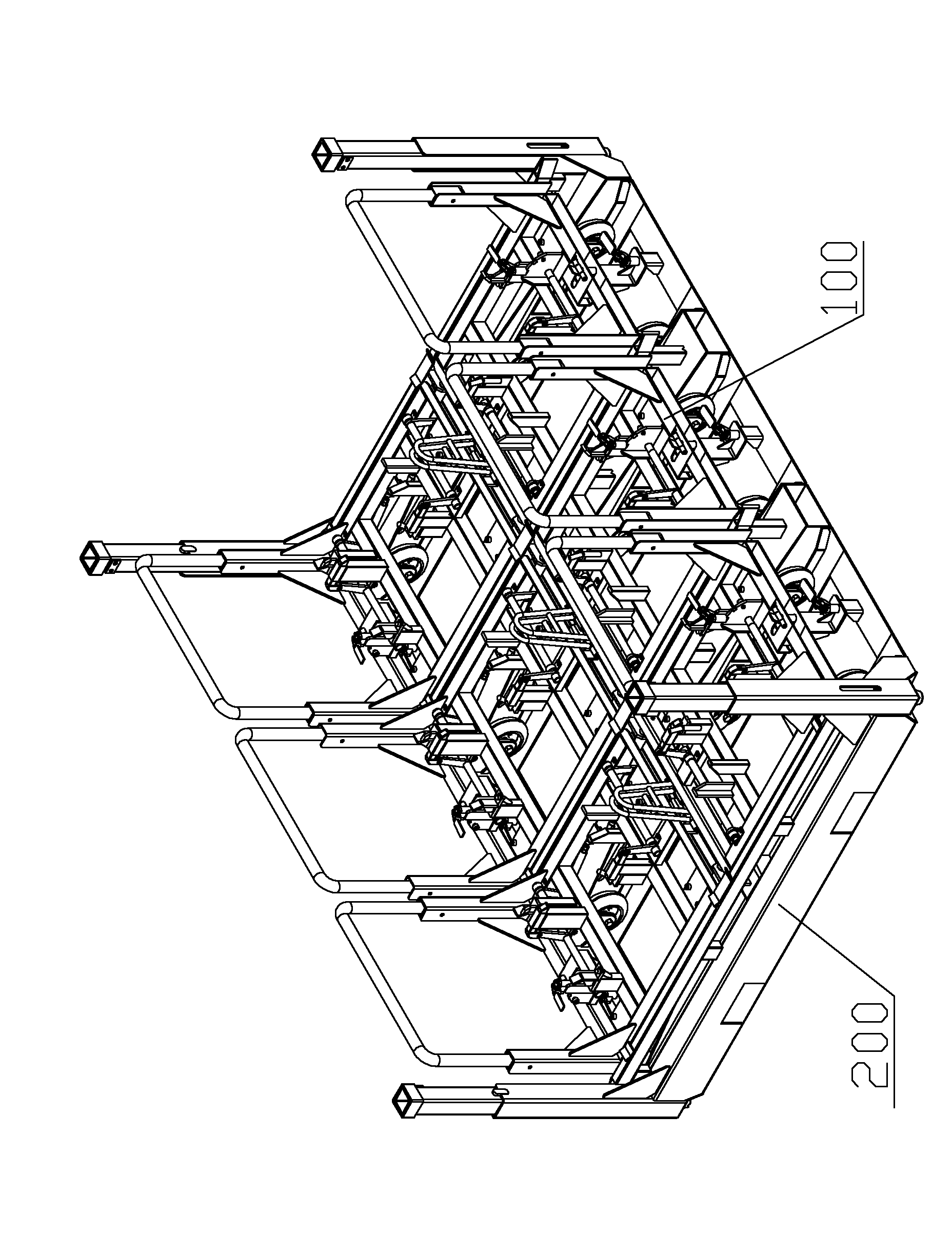
[0041] figure 2 It shows the structure of the engine rack in this embodiment according to the present invention. Such as figure 2 As shown, the engine material rack in this embodiment has an engine material rack assembly, and the engine material rack assembly includes a bottom frame 200 and six material rack trolleys 100 . Six rack trolley stations are arranged on the underframe 200 , and the six rack trolleys 100 are divided into two rows, which are respectively symmetrically arranged in the rack trolley stations of the underframe 200 .

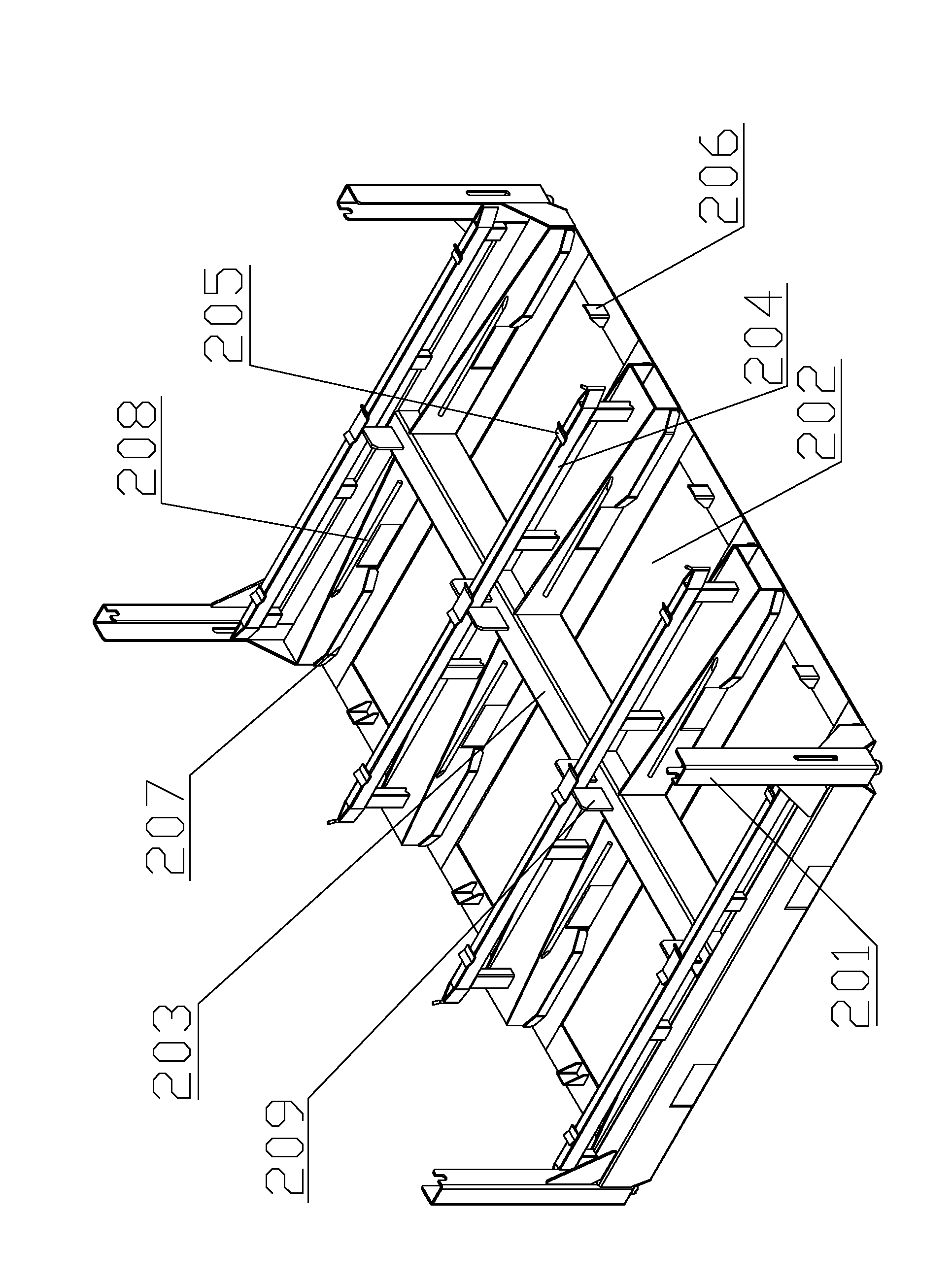
[0042] image 3 The structure of the underframe in one embodiment of the engine rack according to the present invention is shown. Such as image 3 As shown, the underframe is a quadrilateral frame structure, and the six rack trolley stations 202 are divided into two rows, and are symmetrically arranged on the underframe with the beam 203 as the axis of symmetry, and each rack trolley station 202 has an inlet port and In the closed end...

Embodiment 2

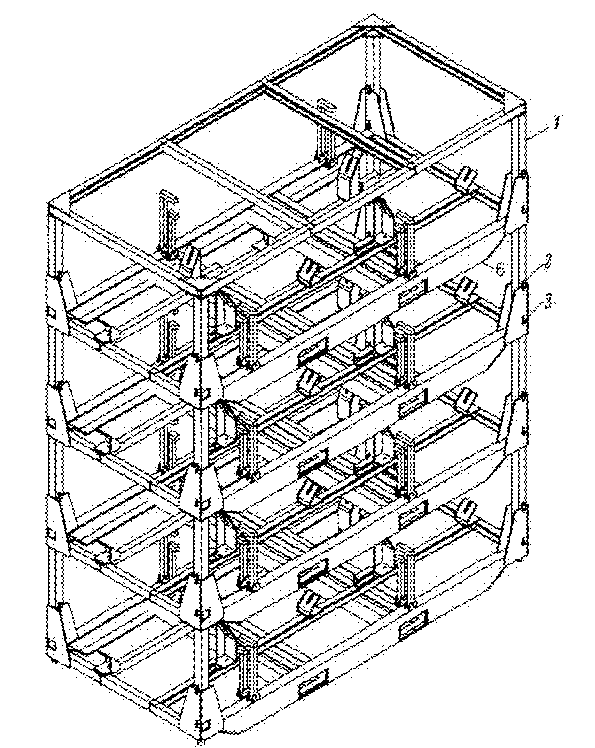
[0052] Figure 7 It shows the structure of the engine rack in this embodiment according to the present invention. Such as Figure 7 As shown, the engine material rack in this embodiment has two engine material rack assemblies as described in Embodiment 1, and is stacked through the upright column at the vertical station on the bottom frame, thereby saving the engine material rack. Space. The structure of the engine rack assembly in this embodiment is the same as that of the engine rack assembly in Embodiment 1.


PUM


Abstract

The invention discloses an engine material frame, which comprises at least one engine material frame assembly which comprises an underframe and a plurality of material frame trolleys. A plurality of material frame trolley stations are arranged on the underframe, the plurality of material frame trolleys are correspondingly arranged in the material frame trolley stations, and one engine setting station is respectively and correspondingly arranged on each material frame trolley. The engine material frame has the following advantages that: 1 the material frame trolleys and the corresponding underframe are arranged so that transportation of engines is convenient, fast and labor-saving, and labor intensity of operating personnel is reduced greatly; and 2 the engine material frame can transport a plurality of engines of different models and specifications simultaneously, thereby improving transporting efficiency and being capable of guaranteeing transporting security.

Description

technical field [0001] The invention relates to a material transportation device, in particular to a material rack for placing an engine. Background technique [0002] The publication number is CN2928755, and the disclosure date is August 1, 2007. The Chinese patent document titled "engine logistics material rack" discloses a patented engine logistics material rack, such as figure 1 As shown, it is best composed of four layers of single-layer rack stacking devices. The single-layer material rack has a frame 6, the frame is installed and connected with a supporting part and a positioning part for placing the engine, and the four corners of the frame are respectively installed and connected with a wrapping corner frame, and in the wrapping corner frame, the key pin 2 and the pin shaft 3 are respectively movable. The supporting rods 1 stacked on the single-layer material rack are described. Although this patent can load multiple engines at one time, due to the inaccurate posi...

Claims


Application Information

Patent Timeline
Patent Type & Authority Applications(China)
IPC IPC(8): B65D85/68B65D61/00B65D21/032B65D25/10B65D25/24
Inventor 王琼
Owner 上海众德金属制品启东有限公司
Why Eureka
Try Eureka