Actuator cylinder position locking and unlocking mechanism

A technology of unlocking mechanism and actuator, applied in the direction of fluid pressure actuating device, etc., can solve the problems of large unlocking force, small locking force, easy to get stuck, etc., and achieve the effect of high reliability

Inactive Publication Date: 2012-06-27
JINCHENG NANJING ELECTROMECHANICAL HYDRAULIC PRESSURE ENG RES CENT AVIATION IND OF CHINA
View PDF5 Cites 15 Cited by
  • Summary
  • Abstract
  • Description
  • Claims
  • Application Information

AI Technical Summary

Problems solved by technology

[0003] Disadvantages of this locking technology: the locking force is small; the required unlocking force is large; the steel ball 23 and the armature 24 are easily stuck, and the reliability is not high

Method used


Image

  • Actuator cylinder position locking and unlocking mechanism
  • Actuator cylinder position locking and unlocking mechanism
  • Actuator cylinder position locking and unlocking mechanism

Examples


Embodiment Construction

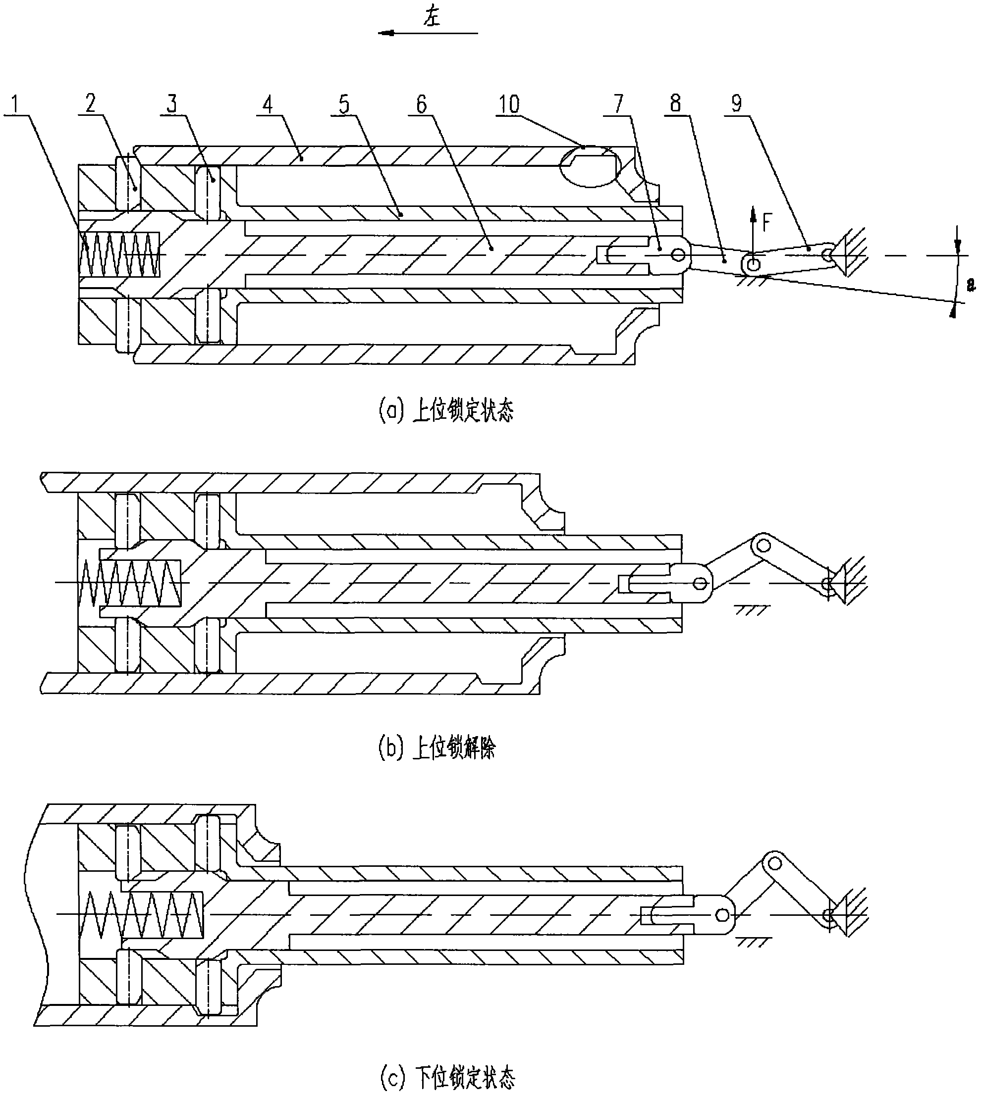
[0019] The present invention will be further described in detail below in conjunction with the accompanying drawings and embodiments. Please refer to the attached Figure 2-5 .

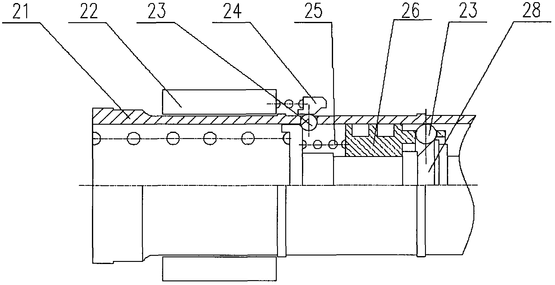
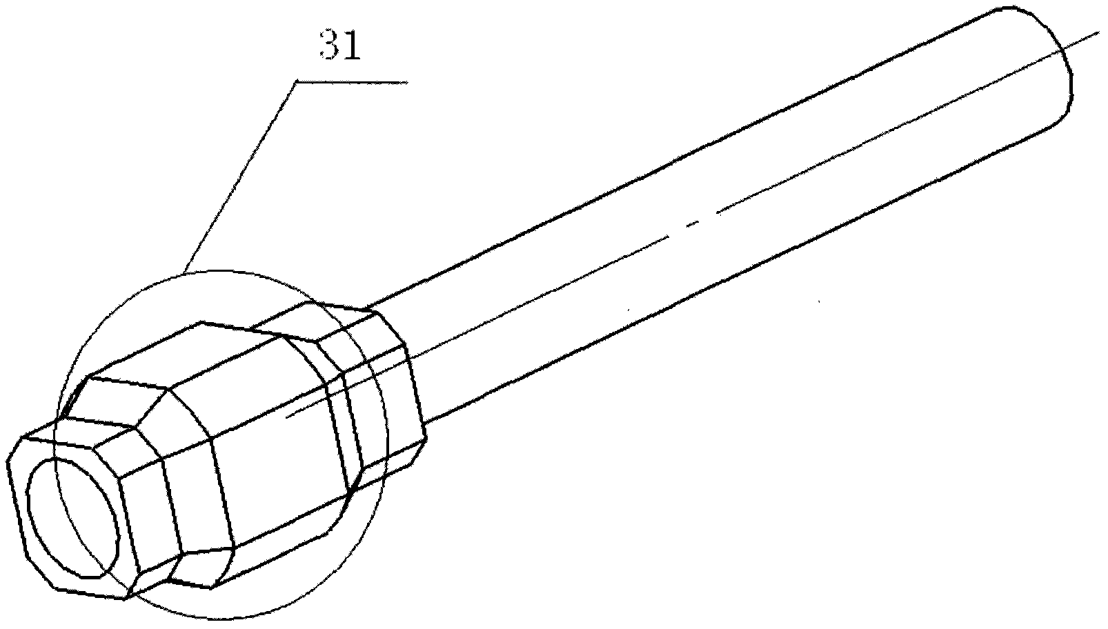
[0020] A position locking and unlocking mechanism for an actuator, comprising a cylinder body 4, a piston 5, and a push rod 6, the push rod 6 is installed in the piston 5, one end of the push rod 6 is provided with a cavity, in which a spring 1 is installed, and the other end is provided with a cavity There is a hole, connected with the first connecting rod 7 with a cylindrical boss, the first connecting rod 7, the second connecting rod 8, and the third connecting rod 9 are sequentially hinged, and the other end of the third connecting rod 9 is relatively fixed; One end close to the cavity of the push rod 6 is provided with a radial hole 51 for installing the upper lock pin 2 and the lower lock pin 3, the radial holes 51 are evenly distributed along the circumference, and grooves are arranged in the ...


PUM


Abstract

The invention relates to an actuator cylinder position locking and unlocking mechanism, which comprises a cylinder body (4), a piston (5) and an ejector rod (6). The ejector rod (6) is mounted in the piston (5), a cavity is arranged at one end of the ejector rod (6), a spring (1) is mounted in the cavity, a hole is arranged at the other end of the ejector rod (6), the other end of the ejector rod is connected with a first connecting rod (7) with a cylindrical boss, the first connecting rod (7), a second connecting rod (8) and a third connecting rod (9) are hinged sequentially, and the other end of the third connecting rod (9) is fixed relatively. Radial holes (51) used for mounting an upper lock pin (2) and a lower lock pin (3) are arranged at one end of the piston (5) close to the cavity of the ejector rod (6) and are distributed circumferentially, and grooves are arranged in the radial holes (51). An annular groove (10) is arranged in the cylinder body (4) and the lower lock pin (3) can be clamped into the annular groove (10). The upper position and the lower position of a hydraulic/pneumatic actuator cylinder can be locked by the aid of the actuator cylinder position locking and unlocking mechanism which is high in locking force, low in unlocking force and high in reliability.

Description

technical field [0001] The invention relates to a position locking and unlocking mechanism of an actuator, which is mainly applied to a hydraulic / pneumatic actuator requiring up and down position locking. Background technique [0002] At present, the position locking of hydraulic / pneumatic actuator mostly adopts the form of "floating piston + steel ball". figure 1 As shown, the cylinder body 21 is fixed, and the piston 28 moves. When the upper lock is in place, the position of the steel ball 23 is limited by the armature 24, and the piston 28 is restricted by the steel ball 23 and cannot be ejected, thereby realizing the upper lock. When unlocking, the electromagnet 22 is energized, the armature 24 is sucked in, the steel ball 23 is loosened, and the piston 28 is ejected. In the same way, the lower locking is realized by using the spring 25, the floating piston 26 and the steel ball 23. [0003] The disadvantages of this locking technology are: the locking force is small; ...

Claims


Application Information

Patent Timeline
Patent Type & Authority Applications(China)
IPC IPC(8): F15B15/26F15B15/20
Inventor 翟笑天李华凤
Owner JINCHENG NANJING ELECTROMECHANICAL HYDRAULIC PRESSURE ENG RES CENT AVIATION IND OF CHINA
Why Eureka
Try Eureka