An axial positioning device

A technology of axial positioning and bearing bush, applied in the direction of bearing components, shafts and bearings, rigid brackets of bearing components, etc., to achieve the effect of convenient installation, replacement and maintenance, high reliability, and easy installation, replacement and maintenance.

Active Publication Date: 2014-10-22
西安航天泵业有限公司
View PDF3 Cites 0 Cited by
  • Summary
  • Abstract
  • Description
  • Claims
  • Application Information

AI Technical Summary

Problems solved by technology

It solves some shortcomings of existing axial positioning devices

Method used


Image

  • An axial positioning device

Examples


Embodiment Construction

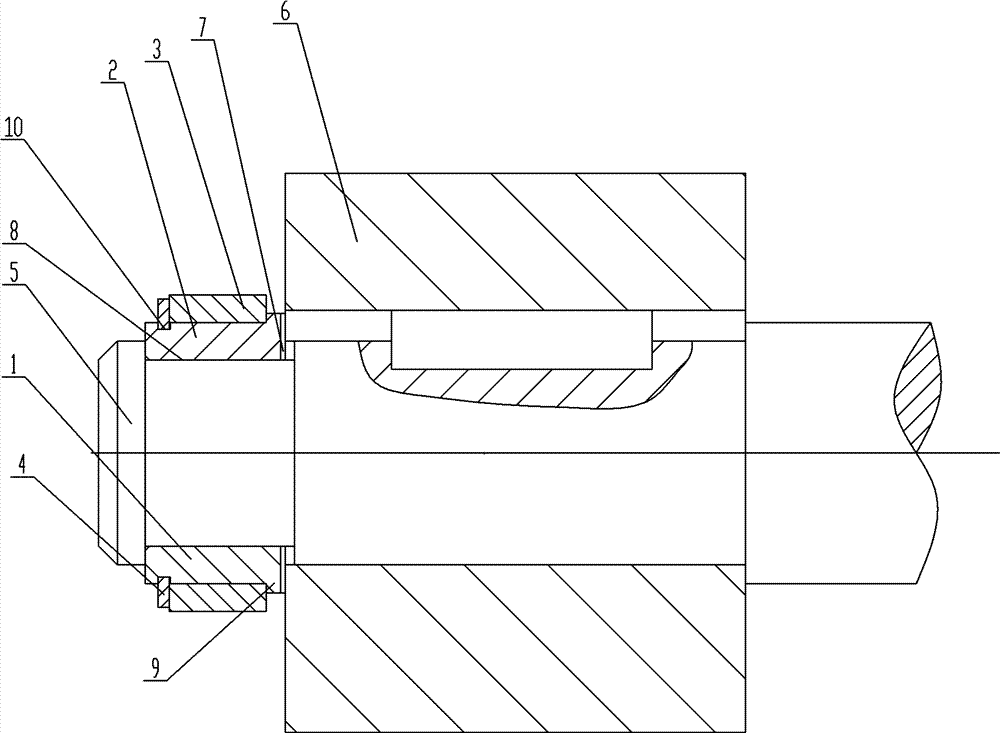
[0018] The structure of the rotor axial positioning device of the present invention is shown in figure 1 , including half bearing bush 1, half bearing bush 2, collar 3, shaft circlip 4, shaft 5, rotor 6, gasket 7; two half bearing bushes 1, 2 are embedded in the annular groove on the shaft 5 to bear the axial Gasket 7 is used to adjust the gap between the bearing bush and the end face of the rotor; the collar 3 is set outside the two half bearing bushes 1 and 2 to fix the bearing bush and bear the radial force that the bearing bush may generate; the shaft circlip 4 is installed on the two half bearing bushes The collar 3 is axially fixed in the groove on the half bearing bush.

[0019] The two half-bearing bushes 1 and 2 are made of stainless steel or non-metallic materials, and after each size is processed together, they are separated into two halves, marked with the same marks respectively and stored in pairs. Ensure that the axial dimensions of the grooves into which the s...


PUM


Abstract

The invention relates to an axial positioning structure. The axial positioning structure comprises an annular slot which is arranged on an outer stretching end of a shaft, two half bushing brushes which are embedded in the annular slot, a sleeve ring which is sleeved outside the two half shaft bushings and an elastic retainer ring, wherein a retainer ring slot which is arranged outside and a limiting step which is arranged inside are arranged on outer circumferential surfaces of the two half shaft bushings; the elastic retainer ring is blocked in a retainer ring slot; and the sleeve ring is arranged between the elastic retainer ring and the limiting step. The axial positioning device solves the technical problem that the current axial positioning structure is difficult to mount and dismount, and a locking gasket is easily damaged in a dismounting process, has a small integral axial dimension, a large bearing axial force, a broad application range, high reliability, and is convenient to mount, change and maintain. The axial positioning device is very convenient to mount, change and maintain as the base structure is simple.

Description

technical field [0001] The invention relates to an axial positioning structure, in particular to an axial positioning structure for a rotating rotor. Background technique [0002] Existing axial positioning structures for rotors include lock nuts, circlips, cotter pins, and shaft head screw structures. The size of the lock nut is large, and the thread cannot bear a large axial force, and it must also prevent circumferential rotation; neither the circlip nor the cotter pin can bear large axial force; the shaft head screw structure generally adopts a shaft head screw and A locking washer is used to axially locate the rotor. This structure is difficult to install and disassemble and the locking washer is easily damaged during assembly and disassembly. Contents of the invention [0003] The object of the present invention is to propose an axial positioning structure for a rotating rotor. It solves some of the disadvantages of existing axial positioning devices. [0004] Tec...

Claims


Application Information

Patent Timeline
Patent Type & Authority Patents(China)
IPC IPC(8): F16C35/10
Inventor 马玉琴朱保民席建厂吕秋洁张发杰刘晓洪杜军伟王明星盛涛
Owner 西安航天泵业有限公司
Why Eureka
Try Eureka