Ultrasonic levitation and air floatation mixed suspension damping device

A suspension device, ultrasonic technology, applied in the direction of shock absorber, shock absorber-spring combination, shock absorber, etc., to achieve the effect of simple structure, small low-frequency vibration reduction, and easy operation

Inactive Publication Date: 2012-06-27
JILIN UNIV
View PDF5 Cites 14 Cited by
  • Summary
  • Abstract
  • Description
  • Claims
  • Application Information

AI Technical Summary

Problems solved by technology

[0008] Aiming at the problems of cyclone phenomenon, air hammer vibration and suspension stiffness of a single air flotation device, the present invention provides a hybrid suspension vibration damping device of ultrasonic suspension and air flotation

Method used


Image

  • Ultrasonic levitation and air floatation mixed suspension damping device
  • Ultrasonic levitation and air floatation mixed suspension damping device
  • Ultrasonic levitation and air floatation mixed suspension damping device

Examples


Embodiment 1

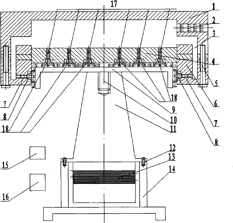
[0030] see image 3 , the air bearing (4) is fixed together with the working platform (1) and the platform base (6) by bolts (5). Ultrasonic transducer (11) is fixedly connected by screw (10) ultrasonic transducer disk (9). The ultrasonic transducer (11) is fixedly connected with the instrument support (14) through screws (12). The ultrasonic transducer (11) is connected with the ultrasonic signal generator (15). The air bearing (4) is placed on the ultrasonic transducer disk (9). The gas that air compressor (16) comes out enters air inlet (2) after filtering.

[0031]Its working principle is: the working platform (1), platform base (6) and air bearing (4) are connected together by bolts (5), when the air from the air compressor (17) is filtered, it enters the The air inlet (2), and then the high-pressure gas enters the axial orifice (17) and the pressure chamber (18), and part of the gas enters the flow channel (3), and flows to the radial orifice (7) and the pressure cha...

Embodiment 2

[0033] see Figure 4 , the working platform (1), platform base (6) and air bearing (4) are connected together by bolts (5), when the gas from the air compressor (16) enters the air inlet ( 2), and then the high-pressure gas enters the axial orifice (17) and the axial spherical pressure chamber (19), and part of the gas enters the flow channel (3), and flows to the radial orifice (7) and the radial Spherical pressure chamber (20). The gas from the axial spherical pressure chamber (19) acts on the upper surface of the ultrasonic transducer disc (9), and the gas from the radial spherical pressure chamber (20) acts on the side of the ultrasonic transducer disc (9) superior. This constitutes an air flotation working condition. The ultrasonic transducer disc (9) is fixedly connected with the ultrasonic transducer (11) through the screw (10), and the ultrasonic transducer (11) is fixedly connected with the instrument bracket (14) through the screw (12), and the ultrasonic signal i...


PUM


Abstract

The invention relates to a novel ultrasonic levitation and air floatation mixed suspension damping device, fulfills the aim of damping by utilizing the novel ultrasonic levitation and air floatation mixed suspension and belongs to the field of precision driving. An ultrasonic transducer disc is fixedly connected with an ultrasonic transducer. A working platform is fixedly connected with an air floatation bearing. A platform base is fixedly connected with the air floatation bearing. Axial orifices and pressure chambers are distributed on the air floatation bearing. Radial orifices and pressure chambers are distributed on the platform base. The air floatation bearing is placed on the ultrasonic transducer disc. Therefore, the whole connected air floatation bearing is suspended by ultrasonic levitation and air floatation. In the mixed suspension process, the ultrasonic levitation improves the cyclone phenomenon and the vibration of a pneumatic hammer when an air floatation device independently works. The novel mixed suspension device has the advantages that the novel ultrasonic levitation and air floatation mixed suspension damping device is easy to operate, has simple structure and has higher suspension rigidity than the single air floatation device which independently works; and the micro low frequency vibration of the air floatation device is reduced.

Description

technical field [0001] The invention relates to a hybrid suspension damping device adopting ultrasonic suspension and air flotation, which belongs to the field of precision driving. Background technique [0002] With the development of technology, the ultra-precision motion platform has developed into an important component of many high-precision and complex equipment, and the accuracy of its motion mechanism directly determines the accuracy required for device motion. The actuators of traditional ultra-precision motion platforms are mainly composed of contact-type moving pairs and rotating pairs, so there are inevitably friction, wear, heat, etc. between the moving pairs, and the rigid structure cannot better eliminate mechanical The vibration of the structure, and more importantly, the motion precision of this type of structure can only reach the micron level at present. Therefore, it can no longer meet the motion precision requirements of IC manufacturing and ultra-preci...

Claims


Application Information

Patent Timeline
Patent Type & Authority Applications(China)
IPC IPC(8): F16F13/00
Inventor 刘家郡江海刘建芳焦晓阳李晓韬杨志刚
Owner JILIN UNIV
Why Eureka
Try Eureka