Backlight module and television

A technology for a backlight module and a backplane, which is applied in the field of televisions to achieve the effects of good display effect, flexible optical frame design, and increased flexibility

Active Publication Date: 2012-06-27
HISENSE VISUAL TECH CO LTD
View PDF8 Cites 4 Cited by
  • Summary
  • Abstract
  • Description
  • Claims
  • Application Information

AI Technical Summary

Problems solved by technology

[0005] In view of this, the technical problem to be solved by the present invention is to provide a new backlight module, which can effectively avoid the increase in the volume of the bracket caused by the increase of the light mixing distance, the dark shadow of the bracket in the backlight module, and the increase of the optical film. slice thus increasing the cost problem arises

Method used


Image

  • Backlight module and television
  • Backlight module and television
  • Backlight module and television

Examples


Embodiment 1

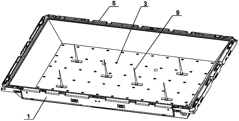
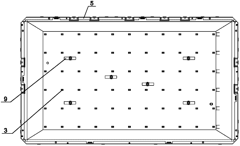
[0021] Figure 5 , Figure 6 It is a structural schematic diagram of an embodiment of the backlight module according to the present invention.

[0022] Such as Figure 5 , Figure 6 As shown, an embodiment of the present invention provides a direct-lit LED backlight module, including an open backplane 1, a reflector 2, an LED light source 3, a diffusion plate 4, and a plastic frame 5. The backplane 1 The inner surface of the backboard 1 is provided with the reflector 2, the LED light source 3 is installed on the bottom of the backboard 1 and passes through the reflector 2, and the open end of the backboard 1 is provided with a supporting platform 11, so The plastic frame 5 is installed around the support platform 11 and fixed on the support platform 11, the diffusion plate 4 is installed on the support platform 11 and fixed by the plastic frame 5, by adjusting the diffusion plate 4 is the area of ​​the contact portion with the support platform 11 on the back plate 1 to sup...

Embodiment 2

[0041] Figure 7 , Figure 8 It is a structural schematic diagram of another embodiment of the backlight module according to the present invention.

[0042] Such as Figure 7 , Figure 8 As shown, another embodiment of the present invention provides another direct-lit LED backlight module, which includes an open back plate 1, a reflector 2, an LED light source 3, a diffuser plate 4, and a plastic frame 5. The inner surface of the board 1 is provided with the reflector 2, the LED light source 3 is installed on the bottom of the backboard 1 and passes through the reflector 2, and the open end of the backboard 1 is provided with a supporting platform 11 , the plastic frame 5 is installed around the support platform 11 and fixed on the support platform 11, the diffusion plate 4 is installed on the support platform 11 and fixed by the plastic frame 5, by placing the The diffuser plate 4 is pasted on the supporting platform 11 to support the diffuser plate 4 .

[0043] Each sid...

Embodiment 3

[0051] This embodiment is basically the same as embodiment one and embodiment two, and its difference is:

[0052] This embodiment provides another direct-lit LED backlight module, which includes an open backplane 1, a reflector 2, an LED light source 3, a diffusion plate 4, and a plastic frame 5. The inner surface of the backplane 1 is provided with The reflector 2, the LED light source 3 are installed on the bottom of the backboard 1 and pass through the reflector 2, the open end of the backboard 1 is provided with a support platform 11, and the plastic frame 5 is installed Around the support platform 11 and fixed on the support platform 11, the diffusion plate 4 is installed on the support platform 11 and fixed by the plastic frame 5, by adjusting the diffusion plate 4 and the back The area of ​​the contact portion of the support platform 11 on the plate 1 and the diffusion plate 4 is pasted on the support platform 11 to support the diffusion plate 4 .

[0053] This soluti...


PUM


Abstract

The invention provides a direct type LED backlight module, which comprises a back plate, a diffusion plate and a rubber frame, and is characterized in that: the opening end of the back plate is provided with a supporting platform; the rubber frame is arranged at the periphery of the supporting platform and fixed on the supporting platform; the diffusion plate is arranged on the supporting platform and fixed by the rubber frame; and the diffusion plate is supported by adjusting an area of a contact area between the diffusion plate and the supporting platform on the back plate and/or adhering the diffusion plate to the supporting platform. The invention also provides a television comprising the backlight module. By the backlight module and the television, problems that the volume of a bracket is increased, the bracket generates a shade in the backlight module and an optical diaphragm is arranged because the light mixing distance is increased are effectively avoided, and the cost of the whole television is obviously reduced.

Description

technical field [0001] The invention relates to the field of electronic products, in particular to a backlight module and a television set including the backlight module. Background technique [0002] At present, the backlight modules used in TV sets all include brackets, such as figure 1 and figure 2 As shown, among them, 1 is the backplane, 3 is the light source, 4 is the diffuser plate, 5 is the plastic frame, 9 is the bracket, in the backlight module of the direct type CCFL (Cold Cathode Fluorescent Lamp cold cathode fluorescent lamp tube), the bracket 9 It plays the role of supporting the diffuser plate 4 and fixing the CCFL light source 3; in the backlight module of the direct type LED (Light Emitting Diode), the bracket 9 only plays the role of supporting the diffuser plate 4 . [0003] For direct-lit LED backlight modules, in order to reduce the number of light sources 3 (that is, LED lamps), it is necessary to increase the light mixing distance of the backlight m...

Claims


Application Information

Patent Timeline
Patent Type & Authority Applications(China)
IPC IPC(8): F21S8/00F21V5/08F21V17/10H04N5/64
CPCG02F1/133603G02F1/133606G02F1/133608G02F1/1335F21V17/10F21S8/00F21V5/08
Inventor 宋志成乔明胜曹建伟
Owner HISENSE VISUAL TECH CO LTD
Why Eureka
Try Eureka