A digital electronic detonator bridge wire welding assembly

A technology of bridge wire welding components and digital electronic detonators, applied in the field of pyrotechnics manufacturing, can solve the problems of device damage, difficult operation, different axes, etc.

Active Publication Date: 2016-01-20
RONGGUI SICHUANG BEIJING TECH
View PDF9 Cites 0 Cited by
  • Summary
  • Abstract
  • Description
  • Claims
  • Application Information

AI Technical Summary

Problems solved by technology

[0004] In order to solve the problem that the bridge wire and the circuit board are not in the same axis, it is difficult to operate during the assembly process, and the device is easily damaged due to the eccentric force, the invention provides a digital electronic detonator bridge wire welding assembly, including a circuit board, metal parts, bridge Wires and wires, the circuit board is designed with grooves and vias matching the metal parts; the metal parts are composed of three parts, which are groove parts, support parts, and bending parts; the groove parts and The grooves on the circuit board are matched; the bridge wire is connected to the wire, and the wire is placed in the groove, and the electrical connection with the metal part is realized by welding; the depth of the groove is half the thickness of the circuit board and the radius of the wire Addition; the support part is located on both sides of the groove along the wire direction, and realizes the electrical connection with the circuit board through the pads on both sides of the groove along the wire direction on the circuit board; the bending part includes Part 1 connected to the part and perpendicular to the groove part, and part 2 connected to part 1; the part 2 passes through the via hole on the circuit board and is electrically connected to the circuit board by welding, and can be manually bent Fold, buckle on the back of the circuit board

Method used


Image

  • A digital electronic detonator bridge wire welding assembly
  • A digital electronic detonator bridge wire welding assembly
  • A digital electronic detonator bridge wire welding assembly

Examples


Embodiment Construction

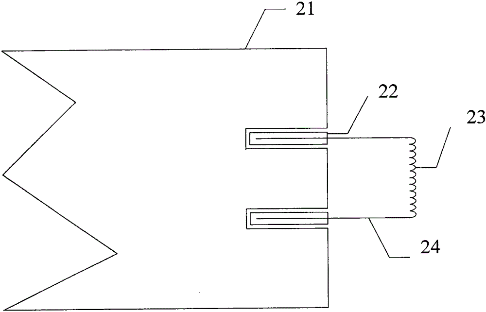
[0025] figure 2 It is a composition schematic diagram of the digital electronic detonator bridge wire welding assembly of the present invention.

[0026] The digital electronic detonator bridge wire welding assembly includes a circuit board 21 , metal parts 22 , bridge wires 23 , and wires 24 .

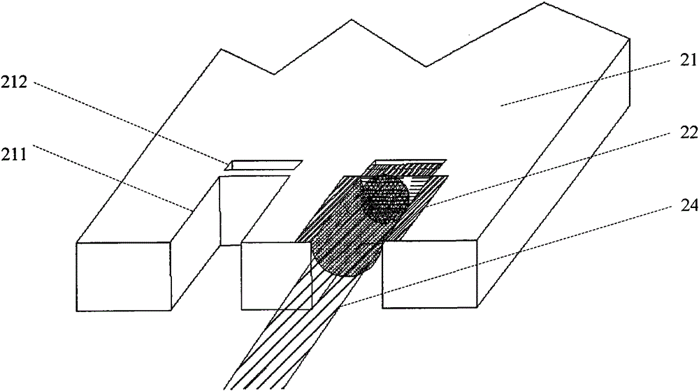
[0027] image 3 It is a schematic diagram of the structure and positional relationship of the circuit board, metal parts, and wires in the present invention.

[0028] The circuit board 21 is designed with a groove 211 and a via hole 212 matching the metal piece 22 .

[0029] Figure 4 It is a schematic diagram of the structure and positional relationship between the circuit board and the metal parts of the present invention.

[0030] The metal piece 22 is composed of three parts, namely a groove part 31 , a supporting part 32 and a bending part 33 .

[0031] The bending portion 33 includes a component one 331 connected to the groove portion 31 and perpendicular to the groove por...


PUM


Abstract

The invention discloses a digital electronic detonator bridge wire welding assembly, which comprises a circuit board, metal pieces, a bridge wire, and leads. The circuit board is designed with grooves and through holes matching with the metal pieces. The metal pieces are composed of three parts, i.e. groove parts, supporting parts, and bending parts, and the groove parts match with the grooves on the circuit board. The bridge wire is in connection with the leads that are placed inside the groove parts, and through welding, electrical connection with the metal pieces can be realized. The depths of the groove parts are the sum of the half of the circuit board thickness and the radius of the leads. The supporting parts are positioned on two sides of the groove parts along the lead direction, and through welding pads on two sides of the grooves on the circuit board along the lead direction, electrical connection with the circuit board can be realized. The bending parts include No.1 components that are connected and perpendicular to the groove parts, and No.2 components in connection with the No.1 components. The No.2 components run through the through holes on the circuit board, through welding, electrical connection with the circuit board can be realized, and the components can be buckled to the backside of the circuit board through artificial bending.

Description

technical field [0001] The invention relates to the technical field of pyrotechnics manufacture, in particular to a digital electronic detonator bridge wire welding assembly. Background technique [0002] The digital electronic detonator includes shell 1, circuit board 2, bridge wire 3, foot wire 4, plug 5, etc., and its positional relationship is attached figure 1 . The shell is generally a metal shell with a circuit board inside. The circuit board is welded with a control chip, a protection circuit composed of electronic components, an energy storage circuit, an ignition circuit, and an auxiliary circuit. At the end, the bridge wire is welded on the circuit board through the wire, and the foot wire extends through the plug to the outside of the shell. [0003] In the prior art, the bridge wire is soldered to the pad at a fixed position on the surface of the circuit board through a wire to realize electrical connection with the circuit board. Therefore, the wire and the c...

Claims


Application Information

Patent Timeline
Patent Type & Authority Patents(China)
IPC IPC(8): F42C19/12
Inventor 李长军李代万王大志赵玉静
Owner RONGGUI SICHUANG BEIJING TECH
Why Eureka
Try Eureka