Method for measuring leakage caused by drilling in geological storage process of CO2

A technology of geological storage and CO2, applied in the direction of detecting the appearance of fluid at the leakage point, using liquid/vacuum degree to measure the liquid tightness, etc., can solve the problems of lack of evaluation means and failure to notice the leakage of injection wells, etc.

Inactive Publication Date: 2012-06-27
INST OF GEOLOGY & GEOPHYSICS CHINESE ACAD OF SCI
View PDF5 Cites 7 Cited by
  • Summary
  • Abstract
  • Description
  • Claims
  • Application Information

AI Technical Summary

Problems solved by technology

but no to CO 2 Research and monitoring are carried out through fault fracture and injection well leakage after i...

Method used


Image

  • Method for measuring leakage caused by drilling in geological storage process of CO2
  • Method for measuring leakage caused by drilling in geological storage process of CO2
  • Method for measuring leakage caused by drilling in geological storage process of CO2

Examples


Embodiment Construction

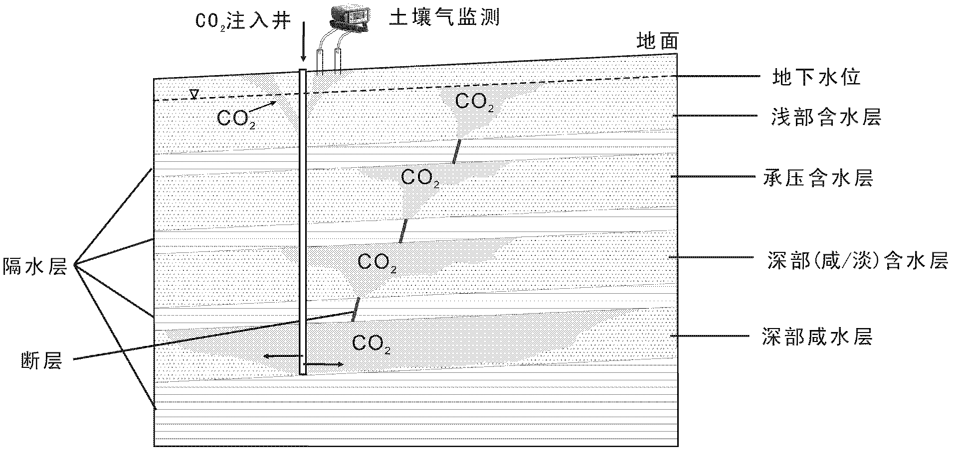
[0016] The basic principle of the technical scheme of the present invention is based on CO 2 The site selection principle and safety evaluation content of geological storage, in CO 2 Before the injection, the background value of the monitoring site should be investigated, and the soil CO around the injection well and the monitoring well should be checked after the injection. 2 Monitor to verify the presence of injected CO 2 of overflow. The content of monitoring should include CO 2 content (volume percent), CO 2 δ of 13 C value (to distinguish CO 2 source), and CO 2 Exhaust flux to atmosphere. see figure 1 , through CO 2 Injection wells inject liquid CO into deep saline aquifers 2 After that, if CO 2 The overflow will gradually overflow to the upper formation through faults, and leak into the soil through injection wells and even monitoring wells. Such as figure 1 Deep brackish / fresh aquifers, confined aquifers, shallow aquifers, and groundwater table are shown in...


PUM


Abstract

The invention relates to a method for measuring gas leakage caused by drilling in the geological storage process of CO2. The method comprises the following main steps of: 1) before the CO2 is injected, performing background value sampling survey on the CO2 content and isotopic composition of soil at the peripheries of an injection well and a monitoring well, and finding out the content and source of the CO2 in the soil under the undisturbed condition; 2) analyzing the carbon isotope of the injected CO2, marking the feature of the isotope, and injecting into a deep salt water layer; and 3) performing sampling analysis on the content and isotope of the CO2 in the soil at positions which are different distances away from the injection well in different time periods, measuring whether the content of the CO2 in the soil is increased or not compared with that under the undisturbed condition, and measuring a relation between the content and CO2 injection. By the method, the CO2 content and isotopic composition of soil gas at the peripheries of the injection well and the monitoring well in the geological storage process of the CO2 can be monitored, so that the influence of the injection well and the monitoring well on the safety of the geological storage process of the CO2 is evaluated.

Description

technical field [0001] The invention relates to a method for monitoring gas leakage, in particular to a CO 2 Method for determination of gas leakage from drilling in geological storage. Background technique [0002] In the context of global climate change, large-scale deep saline CO 2 Geological storage (CCS) is seen as one of the most potential mitigation measures. In order to ensure its safety and storage effectiveness, CO 2 It is very necessary and urgent to monitor the migration status after injection into the deep saline aquifer. At present, the main focus is on the use of geophysical methods to study the CO 2 Diffusion halos and monitoring of water-rock-gas reactions using geochemical methods. However CO 2 Leakage into shallow aquifers or the surface through fault zones and these injection and monitoring boreholes may endanger the ecosystem. So how to effectively monitor CO 2 leakage, for CO 2 Geological storage has important implications. [0003] Safety mon...

Claims


Application Information

Patent Timeline
IPC IPC(8): G01M3/20
Inventor 庞忠和黄天明孔彦龙袁利娟李捷
Owner INST OF GEOLOGY & GEOPHYSICS CHINESE ACAD OF SCI
Why Eureka
Try Eureka