
Device and method for intelligent fertilization

A technology of fertilization device and fertilization method, which is applied in the direction of botany equipment and method, direct liquid fertilizer delivery system, agricultural machinery and implements, etc., and can solve problems such as difficulty in applying fertilizer evenly

Pending Publication Date: 2017-07-04
NANJING WOYANG MACHINERY TECH
View PDF9 Cites 5 Cited by
  • Summary
  • Abstract
  • Description
  • Claims
  • Application Information

AI Technical Summary

Problems solved by technology

[0004] The purpose of the present invention is to solve the technical problem that fertilizers are difficult to apply uniformly in the prior art, and provide an intelligent fertilization device and method. The present invention can improve soil air permeability, retain moisture and store water, and easily apply liquid medicine to plant roots. Conducive to plant growth, improve work efficiency

Method used


Image

  • Device and method for intelligent fertilization
  • Device and method for intelligent fertilization
  • Device and method for intelligent fertilization

Examples


Embodiment 1

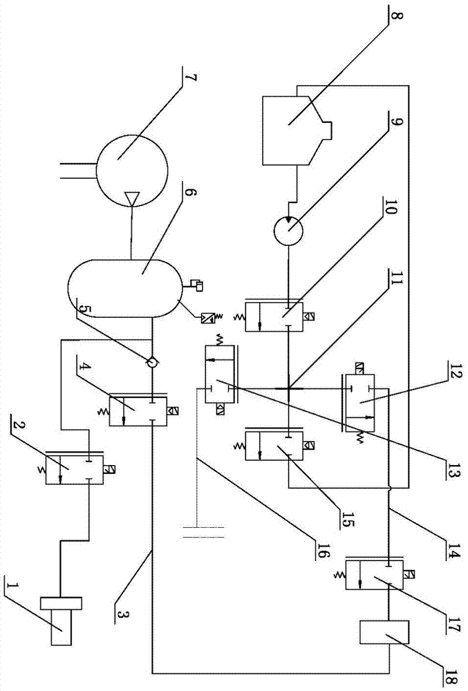
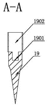
[0039] like Figure 1-8 As shown, an intelligent fertilization device includes a lower support base 21, an air hammer 1 is connected to the upper side of the lower support base 21, the bottom of the lower support base 21 is a hollow tube 18, and the hollow tubes 18 communicate with the pneumatic pipeline 3 respectively. One end and one end of the liquid passage 14, the hollow tube 18 is connected to one end of the lifting driver 20, and one end of the lifting driver 20 is the end where the lifting rod 2001 of the lifting driver 20 is located, the lifting rod 2001 is hollow, and the other end of the lifting rod 2001 is detachable. Connected with the burrower 19, the elevating rod 2001 can perform linear telescopic movement in the lifting driver 20. The lowermost part of the burrower 19 is conical. There is at least one exhaust liquid application hole 1901 on the soil entry device 19 corresponding to the liquid chamber 1902; compressed air is introduced into the pneumatic pipeli...

Embodiment 2

[0062] like Figure 9 As shown, the difference from the embodiment is that the other end of the spare liquid passage line 16 is connected with the hollow pipe 18 of another fertilization device through the solenoid valve two 17, and a new pneumatic line 3 is added, and the new pneumatic line 3 The pipeline 3 is connected to the hollow pipe 18 of another fertilization device through the one-way valve 5 and the electromagnetic valve one 4 in sequence; One end is connected with the other two ends of the tee pipe 27 respectively.

[0063] The working principle of this embodiment is the same as that of Embodiment 1, the difference is that the controller 28 simultaneously controls the actions of the two fertilizing devices, and the actions are completely consistent; this embodiment is suitable for feeding two crops at the same time or around the same During the work of fertilizing different positions of crops.


PUM


Abstract

The invention discloses a device and a method for intelligent fertilization in the technical field of garden machinery. The device comprises a lower supporting base, the upper side of the lower supporting base is connected with an air hammer, the bottom of the lower supporting base is a hollow pipe, and the hollow pipe is communicated with one end of a pneumatic pipeline and one end of a liquid communicating pipeline. The hollow pipe is connected with one end of a lifting rod which is hollow. The lifting rod is arranged on a lifting driver. The other end of the lifting rod is detachably connected with a soil piercing device. The lifting rod can do linear lifting motion in the lifting driver. The lower part of the soil piercing device is in a conical shape. The soil piercing device is internally provided with a liquid communicating cavity which is communicated with an inner cavity of the lifting rod. The soil piercing device corresponding to the liquid communicating cavity is provided with at least an exhaust liquid applying hole. The device and the method improve soil gas permeability, and liquid medicine is easily and uniformly applied in plant root systems, being beneficial for growth of plants.

Description

technical field [0001] The invention relates to a fertilization system, in particular to a fertilization method, a fertilization device and a fertilization control system for applying liquid fertilizer to fruit trees. Background technique [0002] In the garden industry and crops such as fruit trees, in order to make the trees grow vigorously, it is necessary to loosen the soil and fertilize frequently. In the traditional technology, the laborers use manual press-in deep loose soil fertilizer applicators, which can realize deep loose soil, but it can only be applied to soft soil, the pressing depth is shallow, the efficiency is low, the amount of fertilizer can not be quantified, and the machine is heavy and difficult to operate , The labor intensity of the workers is high. [0003] In order to solve the problems existing in the traditional manual processing method, in the prior art, a Chinese invention patent with the patent name of the deep soil loosening fertilizer appli...

Claims


Application Information

Patent Timeline
Patent Type & Authority Applications(China)
IPC IPC(8): A01B49/06A01B39/16A01C23/02A01G29/00G05B19/04
CPCA01B39/16A01B49/06A01C23/02A01G29/00G05B19/04
Inventor 张瑞宏金亦富奚小波张剑峰蔡广林
Owner NANJING WOYANG MACHINERY TECH
Learn More