Image forming apparatus

a technology of forming apparatus and forming tube, which is applied in the direction of electrographic process apparatus, instruments, optics, etc., can solve the problems of uneven toner concentration uneven toner concentration, etc., and achieve uniform toner concentration, and reduce toner concentration changes.

Inactive Publication Date: 2008-11-06
RICOH KK
View PDF37 Cites 23 Cited by
  • Summary
  • Abstract
  • Description
  • Claims
  • Application Information

AI Technical Summary

Benefits of technology

[0022]In view of the foregoing, various illustrative embodiments of the present invention disclosed herein provide an image forming apparatus and a toner supply control method that can maintain a uniform toner concentration in a two-component developer in a developing unit.
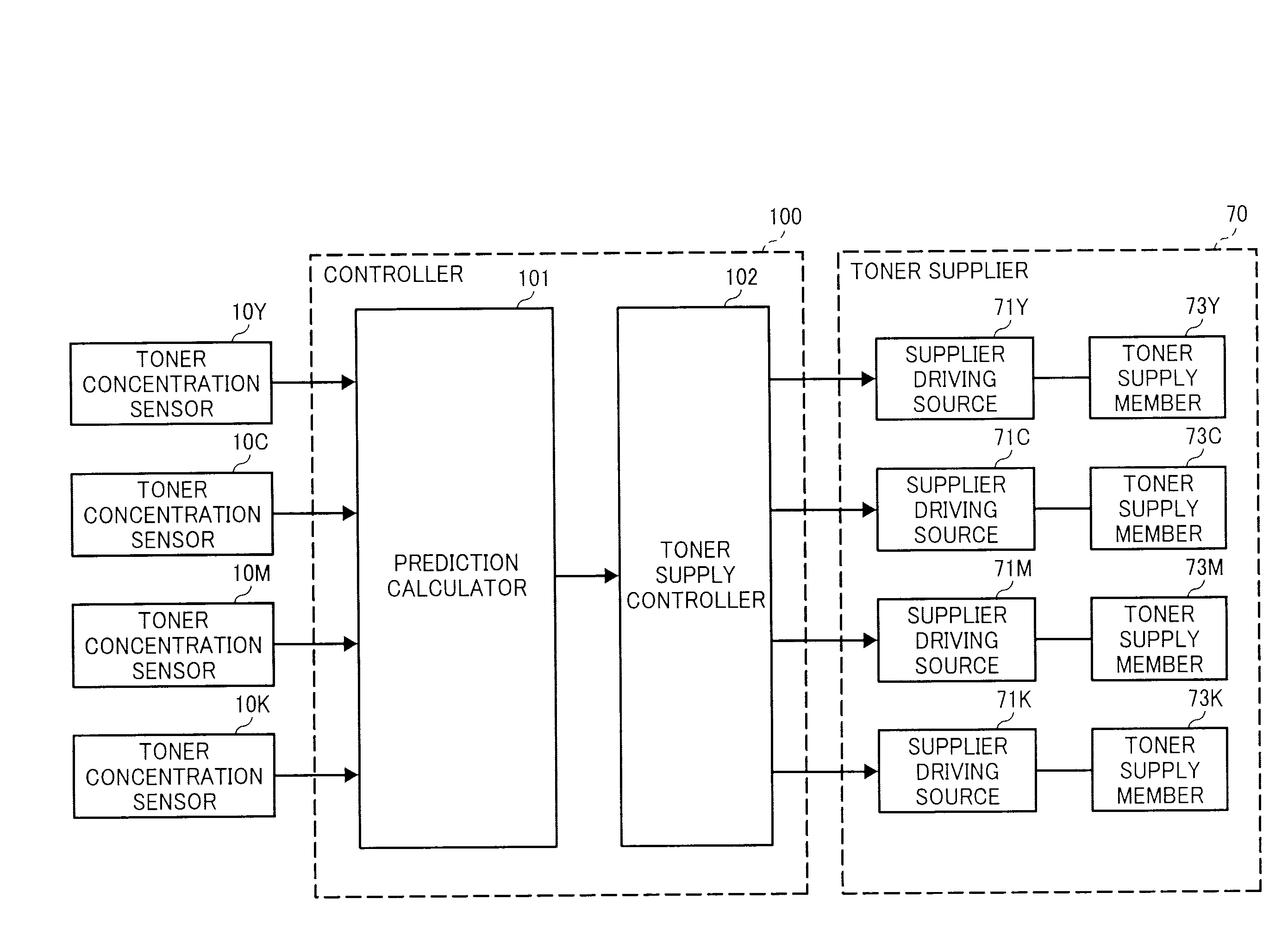
[0023]In one illustrative embodiment of the present invention, an image forming apparatus includes a latent image carrier, a latent image forming unit configured to form an electrostatic latent image on the latent image carrier, a developing unit, a toner supplier including a single driving source and a toner supply member, a toner concentration detector, a prediction calculator, and a toner supply controller. The developing unit develops the latent image with a two-component developer and includes a developer transport member configured to circulate the two-component developer along a developer circulation path, and a developer carrier configured to transport the two-component developer between a development area facing the latent image carrier and the developer circulation path. The toner supplier is connected to the developer circulation path and configured to supply toner at a predetermined supply position to the two-component developer circulating through the developer circulation path by driving a toner supply member with the driving source. The toner concentration detector is located in the developer circulation path and detects, continuously or intermittently, a toner concentration in the two-component developer at a predetermined detection position located upstream of the predetermined supply position in a developer circulation direction. The prediction calculator calculates a prediction of changes in toner concentration in the two-component developer over time at a given prediction position located at the predetermined supply position or the downstream of the predetermined supply position and upstream of a developer feed position where the two-component developer is fed to the developer carrier in the developer circulation direction when toner is not supplied, based on a detection result generated by the toner concentration detector. The toner supply controller reduces the changes in toner concentration in the developer over time at the given prediction position by controlling the driving source based on the prediction calculated by the prediction calculator to adjust an amount of the toner supplied to the two-component developer at the predetermined supply position.
[0024]In another illustrative embodiment, an image forming apparatus includes a latent image carrier, an image information acquisition unit configured to acquire image information, a latent image forming unit configured to form an electrostatic latent image on the latent image carrier according to the image information, a developing unit configured to develop the latent image with a two-component developer, a toner supplier including a single driving source and a toner supply member, a prediction calculator, and a toner supply controller. The developing unit includes a developer transport member that circulates the two-component developer along a developer circulation path, and a developer carrier that transports the two-component developer between a development area facing the latent image carrier and the developer circulation path. The toner supplier is connected to the developer circulation path and supplies toner at a predetermined supply position to the two-component developer circulating through the developer circulation path by driving the toner supply member with the driving source. The prediction calculator calculates, based on the image information, as a prediction, one of changes in a toner concentration over time in the two-component developer passing a given prediction position located at the predetermined supply position or downstream of the predetermined supply position and upstream of a developer feed position where the two-component developer is fed to the developer carrier in the developer circulation direction, caused by developing the latent image according to the image information, when toner is not supplied and a wave form showing a phase opposite that of the changes in the toner concentration over time caused by developing the latent image according to the image information. The toner supply controller reduces the changes in toner concentration over time in the developer at the given prediction position by controlling the driving source based on the prediction calculated by the prediction calculator to adjust an amount of the toner supplied to the two-component developer at the predetermined supply position.
[0025]Yet in another illustrative embodiment, a toner supply control method used in the image forming apparatus described above includes calculating, as a prediction, one of changes in the toner concentration over time in the two-component developer at a given prediction position located at the predetermined supply position or downstream of the predetermined supply position and upstream of a developer feed position where the two-component developer is fed to the developer carrier in the developer circulation direction when toner is not supplied and a wave form showing a phase opposite that of the changes in the toner concentration over time, and adjusting an amount of the toner supplied to the two-component developer at the predetermined supply position by controlling the driving source based on the prediction to reduce the changes in toner concentration over time in the developer at the given prediction position.

Problems solved by technology

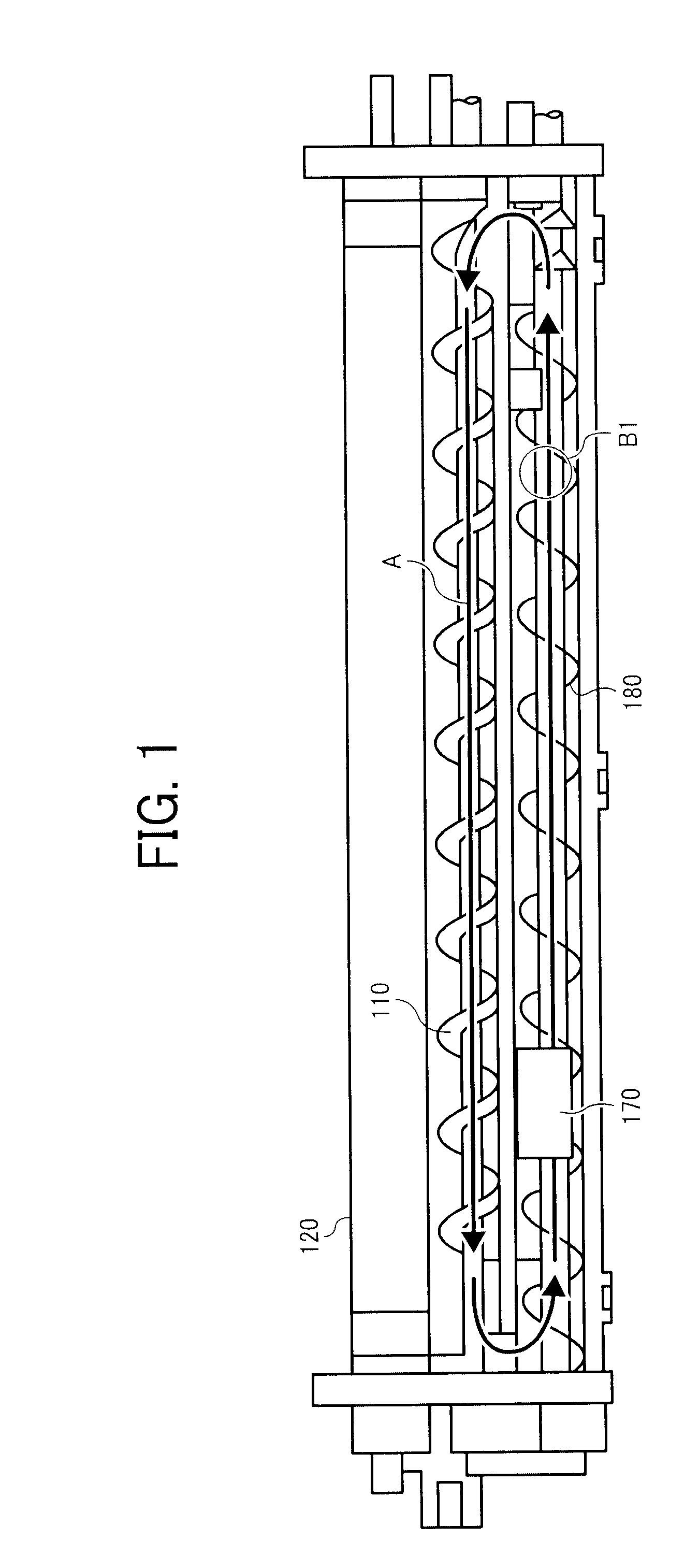
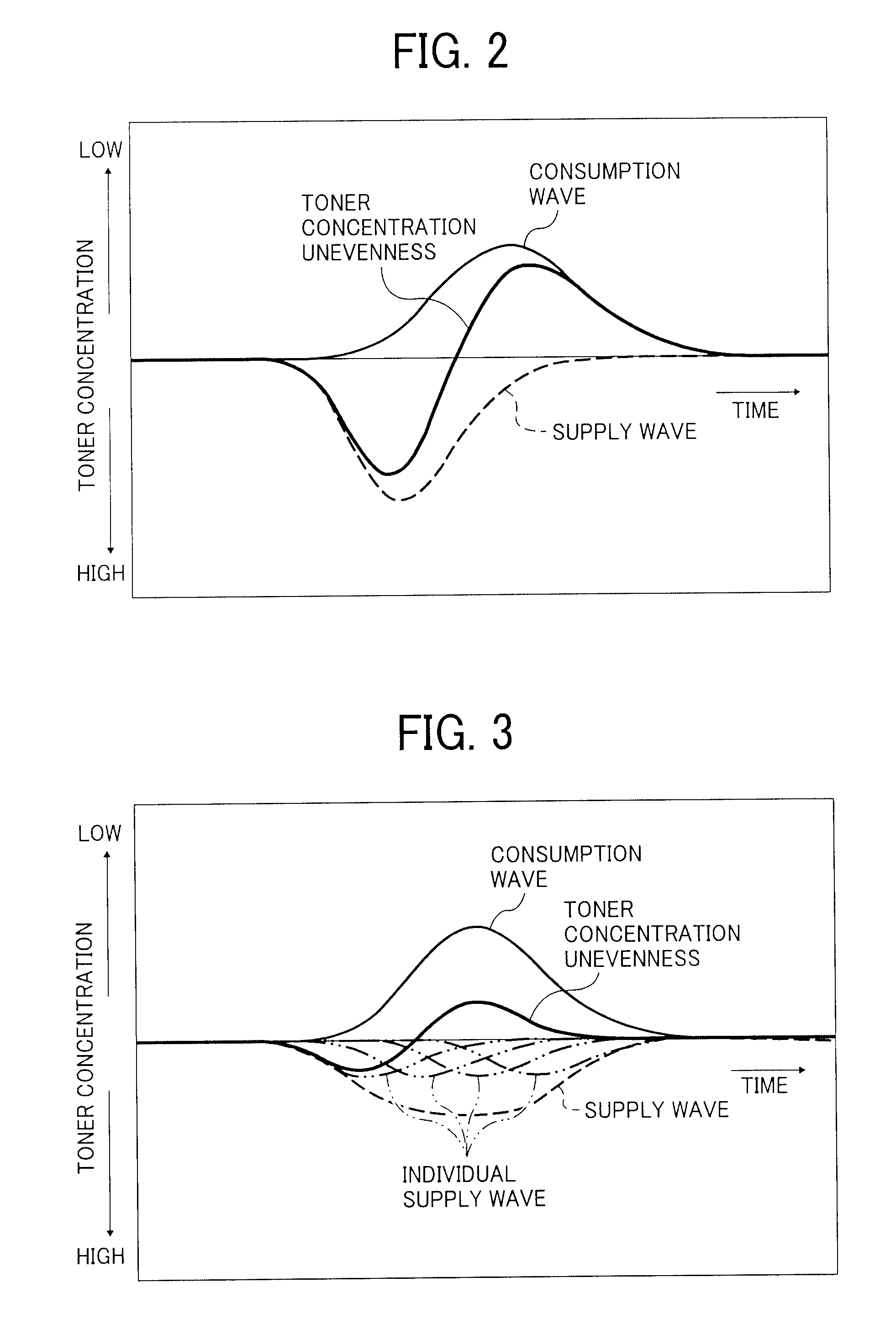
However, in these methods, the toner concentration tends to be uneven in a toner circulation direction in the developing unit, which is hereinafter referred to as toner concentration unevenness.
That is, these consumption waves show examples of toner concentration unevenness or changes in the toner concentration caused by image development.
In particular, toner concentration becomes uneven when the toner is supplied regardless of the consumption wave even if the amount of the toner supplied corresponds to toner consumption, because the toner consumption wave depends on size and location of latent images on the image carrier in actual image formation.
More specifically, the toner concentration in the developer becomes uneven after development of electrostatic latent image if these electrostatic latent images are unevenly distributed on the image carrier.
However, because such a developing unit requires a plurality of driving sources to drive the toner suppliers independently and simultaneously, its cost is relatively high and the developing unit is relatively large.

Method used


Image

  • Image forming apparatus
  • Image forming apparatus
  • Image forming apparatus

Examples


Embodiment Construction

[0049]In describing preferred embodiments illustrated in the drawings, specific terminology is employed for the sake of clarity. However, the disclosure of this patent specification is not intended to be limited to the specific terminology so selected, and it is to be understood that each specific element includes all technical equivalents that operate in a similar manner and achieve a similar result.

[0050]Referring now to the drawings, wherein like reference numerals designate identical or corresponding parts throughout the several views thereof, and particularly to FIG. 5, an electronographic image forming apparatus according to an illustrative embodiment of the present invention is described.

[0051]FIG. 5 is a schematic illustration of the image forming apparatus that is an electronographic printer, for example, and uses a two-component developer including toner and carrier.

[0052]The image forming apparatus includes four process units 1Y, 1M, 1C, and 1K for forming yellow, magenta...


PUM


Abstract

An image forming apparatus includes a latent image carrier, a latent image forming unit, a developing unit, a toner supplier, a toner concentration detector, a prediction calculator, and a toner supply controller. The toner supplier includes a single driving source and supplies toner to a two-component developer at a predetermined supply position by driving a toner supply member with the driving source. The toner concentration detector detects a toner concentration in the developer at a predetermined detection position located upstream of the supply position. The prediction calculator predicts changes in the toner concentration in the developer over time at a prediction position located at the supply position or downstream of the supply position and upstream of a developer feed position to the developer carrier when toner is not supplied, based on a result of the toner concentration detection. The toner supply controller adjusts an amount of the toner supplied based on the prediction.

Description

CROSS-REFERENCE TO RELATED APPLICATIONS[0001]This patent specification claims priority from Japanese Patent Application Nos. 2007-12141, filed on May 1, 2007 and 2008-106335, filed on Apr. 16, 2008, in the Japan Patent Office, the entire contents of each of which are hereby incorporated by reference herein.BACKGROUND OF THE INVENTION[0002]1. Field of the Invention[0003]The present invention generally relates to an image forming apparatus such as a copier, a printer, a facsimile machine, and a multifunction machine including at least two of these functions.[0004]2. Discussion of the Background Art[0005]In general, an electrophotographic image forming apparatus such as a copier, a printer, a facsimile machine, etc., includes a latent image carrier on which an electrostatic latent image is formed, and a developing unit to develop the electrostatic latent image with developer. The developed image is then transferred onto a sheet of recording medium and fixed thereon.[0006]To develop ele...

Claims


Application Information

Patent Timeline
Patent Type & Authority Applications(United States)
IPC IPC(8): G03G15/08
CPCG03G15/09G03G15/0893G03G15/0853G03G15/0849
Inventor KOIZUMI, EICHIKATO, SHINJI
Owner RICOH KK
Why Eureka
Try Eureka