
Coin box locking mechanism

A technology of locking mechanism and cash box, applied in the direction of coin counting, handling coins or valuable banknotes, building locks, etc., can solve problems such as hidden safety hazards, and achieve the effect of solving hidden safety problems

Active Publication Date: 2014-07-02
GRG BAKING EQUIP CO LTD
View PDF3 Cites 0 Cited by
  • Summary
  • Abstract
  • Description
  • Claims
  • Application Information

AI Technical Summary

Problems solved by technology

[0003] The object of the present invention is to provide a locking mechanism for a coin cash box, which can effectively prevent the coin cash box from being opened again after use, thus solving the hidden safety problems existing in the prior art

Method used


Image

  • Coin box locking mechanism
  • Coin box locking mechanism
  • Coin box locking mechanism

Examples


Embodiment Construction

[0021] In order to make the object, technical solution and advantages of the present invention clearer, the present invention will be further described in detail below in conjunction with the accompanying drawings.

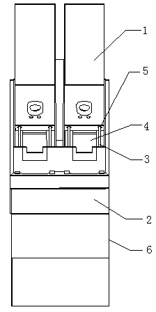
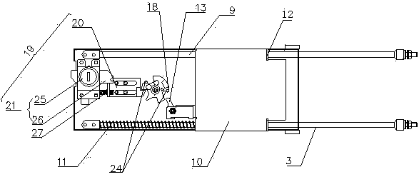
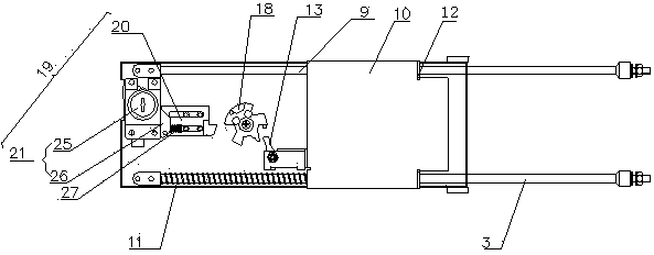
[0022] Such as figure 1 , figure 2 Shown is a schematic structural view of the coin box and the coin box body 1 of the present invention. The coin cash box includes a coin cash box body 1 , a coin processing module 2 , a pair of push rods 3 , a coin receiving port 4 , a pair of push rod insertion holes 5 , and track equipment 6 . The coin processing module 2 is arranged on the track equipment 6, and the coin processing module 2 has a coin receiving port 4, and a pair of push rods 3 are arranged on both sides of the coin receiving port 4. A pair of push rod insertion holes 5 are provided on the bottom cover 7 of the coin box body 1 . The push rod insertion hole 5 corresponds to the position of the push rod 3 , and the push rod 3 is inserted into the push rod in...


PUM


Abstract

The invention discloses a coin box locking mechanism. The coin box locking mechanism comprises a ratchet device, a ratchet drive part matched with the ratchet device and a ratchet release device. By means of the coin box locking mechanism disclosed by the invention, the coin box can be effectively prevented from being opened at second time after being used, and the potential safety hazard is avoided.

Description

technical field [0001] The invention relates to a locking mechanism of a coin cash box, in particular to a device for preventing the coin cash box from being opened again after being used. Background technique [0002] Most of the coin cash boxes currently on the market have similar structures, consisting of an accommodating chamber for accommodating coins, a cash box cover, and a coin cash box shell. The accommodating cavity is mainly used for storing and adding coins, and the cash box shell is used for containing the box body of the accommodating cavity. The cash box cover is covered on the cash box shell, and a coin outlet is opened on the cash box cover. The common locking mechanism of the coin cash box is equipped with a set of guide sliders on one side of the coin outlet, a gate is slidably installed on the guide slider, and an elastic member provides spring force for the gate to the direction of the coin outlet. To keep the coin outlet closed, there are a pair of shi...

Claims


Application Information

Patent Timeline
Patent Type & Authority Patents(China)
IPC IPC(8): G07D9/06E05B65/52
Inventor 张博闻廖卫军张伟霞吴爱明
Owner GRG BAKING EQUIP CO LTD
Learn More