
High pressure common rail fuel injection control system for low speed marine diesel engine

A marine diesel engine, high-pressure common rail technology, applied in fuel injection control, engine control, electrical control, etc., can solve the problem of difficult to achieve real-time control of fuel injection quantity, and achieve the effect of increasing pressure, improving frequency response, and avoiding closing delay.

Inactive Publication Date: 2015-09-23
NANJING UNIV OF AERONAUTICS & ASTRONAUTICS
View PDF5 Cites 0 Cited by
  • Summary
  • Abstract
  • Description
  • Claims
  • Application Information

AI Technical Summary

Problems solved by technology

[0004] The technical problem to be solved by the present invention is: to overcome the fact that the flow control in the prior art is an open-loop system, it is difficult to realize the real-time control of the fuel injection quantity, and to provide a low-speed marine diesel engine high-pressure common rail fuel injection control system, a high-pressure flow meter and a low-pressure servo The system constitutes a closed-loop feedback control system. The twin-screw rotameter accurately calculates the fuel injection volume required for one injection, and the low-pressure servo system controls the position of the valve stem to control the connection between the high-pressure oil inlet and high-pressure oil outlet. Opening degree, so as to achieve the purpose of real-time control of fuel injection volume, easy to achieve flexible control

Method used


Image

  • High pressure common rail fuel injection control system for low speed marine diesel engine
  • High pressure common rail fuel injection control system for low speed marine diesel engine
  • High pressure common rail fuel injection control system for low speed marine diesel engine

Examples


Embodiment Construction

[0026] The present invention is described in further detail now in conjunction with accompanying drawing. These drawings are all simplified schematic diagrams, which only illustrate the basic structure of the present invention in a schematic manner, so they only show the configurations related to the present invention.

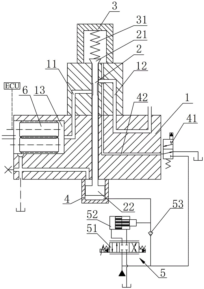
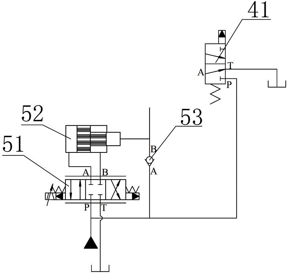
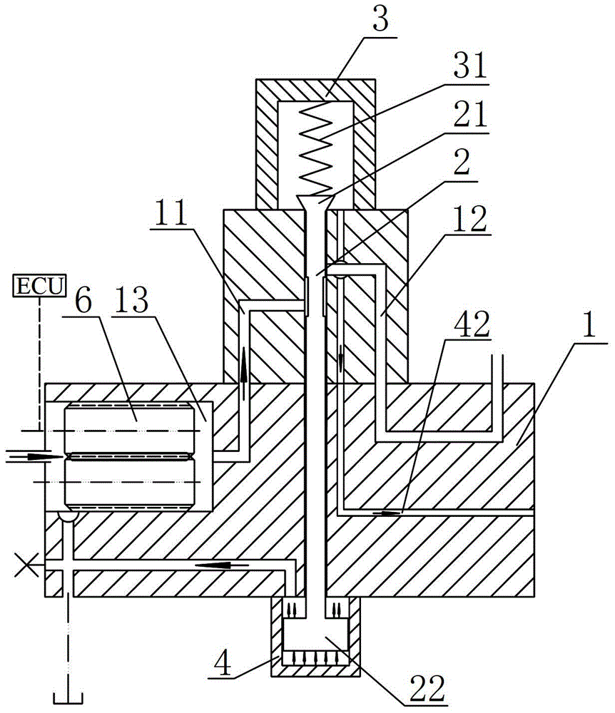
[0027] like Figure 1~6 The best embodiment of a high-pressure common rail fuel injection control system for a low-speed marine diesel engine shown in the present invention includes a high-pressure valve body 1 and a valve core 2, and the high-pressure valve body 1 has a high-pressure oil inlet oil passage 11 and a high-pressure oil outlet Road 12, the valve core 2 includes a valve stem and a valve head 21 and a piston body 22 respectively located at both ends of the valve stem. The high-pressure valve body 1 has a through hole for accommodating the valve stem. The movement inside makes the high-pressure oil inlet circuit 11 and the high-pressure oil outlet c...


PUM


Abstract

The invention relates to a low-speed marine diesel engine high-pressure common rail fuel oil spraying control system, which comprises a high-pressure valve body and a valve core, wherein parts, positioned at the two ends of a through hole, on the high-pressure valve body are respectively provided with a pilot end cover for installing a valve head and a main valve end cover for installing a piston body, an elastic element for providing the pretightening force for the valve head is arranged in the pilot end cover, a low-pressure servo system for providing the hydraulic driving force for a rodless cavity of the main valve end cover is connected onto the rodless cavity of the main valve end cover, a metering cavity is arranged in a position positioned on a high-pressure oil inlet oil path in the high-pressure valve body, and a high-pressure flow rate meter is arranged in the metering cavity. The low-speed marine diesel engine high-pressure common rail fuel oil spraying control system provided by the invention is used for low-speed marine diesel engine high-pressure common rail fuel oil spraying control, on one hand, the pressure boosting effect of a pressure boosting cylinder is utilized, the valve core is pushed to be fast opened, on the other hand, the electro-hydraulic servo control principle is utilized, and the oil spraying quantity is controlled in real time.

Description

technical field [0001] The invention relates to the technical field of fuel injection control for diesel engines, in particular to a high-pressure common rail fuel injection control system for low-speed marine diesel engines. Background technique [0002] With the development of my country's shipbuilding industry towards ultra-large and high value-added ships, higher requirements are put forward for the independent manufacturing, intelligence and large-scale of its supporting diesel engines. From the perspective of the development of modern marine fuel injection systems, low-speed marine high-pressure common rail fuel injection systems must have the characteristics of fast response, good opening and closing, stable system, and good atomization. like Figure 7 As shown, the current mainstream is the high-pressure common rail fuel injection control system used in the SULZERRT-Flex marine EFI diesel engine series. It mainly includes the main valve body and the spool. The main ...

Claims


Application Information

Patent Timeline
Patent Type & Authority Patents(China)
IPC IPC(8): F02D41/38F02D41/14
Inventor 游有鹏康双琦
Owner NANJING UNIV OF AERONAUTICS & ASTRONAUTICS
Learn More