A Quick-start Switching Power Supply Powered by Auxiliary Winding

A switching power supply and auxiliary winding technology, applied in the direction of electrical components, output power conversion devices, etc., can solve the problems of short turn-on time and increase cost, and achieve the effect of reducing turn-on time, avoiding secondary turn-on and reducing turn-on time.

Active Publication Date: 2016-01-13
SOUTHEAST UNIV
View PDF4 Cites 0 Cited by
  • Summary
  • Abstract
  • Description
  • Claims
  • Application Information

AI Technical Summary

Problems solved by technology

Now some high-end products on the market get a very short turn-on time through some complex peripheral circuits, but this is at the cost of increasing costs

Method used


Image

  • A Quick-start Switching Power Supply Powered by Auxiliary Winding
  • A Quick-start Switching Power Supply Powered by Auxiliary Winding
  • A Quick-start Switching Power Supply Powered by Auxiliary Winding

Examples


Embodiment Construction

[0018] Below in conjunction with accompanying drawing, the technical scheme of invention is described in detail:

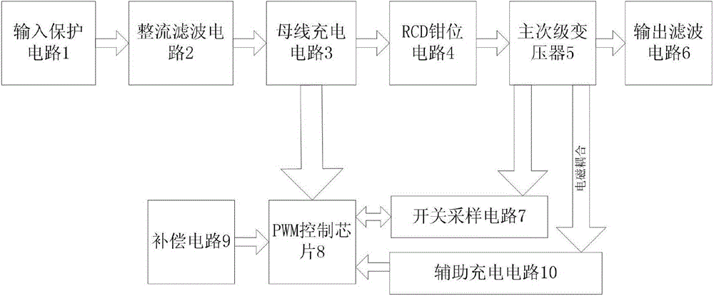
[0019] Such as figure 1 As shown, a fast turn-on switching power supply based on the structure of the flyback switching power supply and powered by the auxiliary winding includes an input protection circuit 1, a rectification filter circuit 2, a bus charging circuit 3, an RCD clamping circuit 4, a transformer 5, and an output filter Circuit 6, switch sampling circuit 7, PWM control circuit 8, auxiliary charging circuit 10. Input protection circuit 1 is sequentially connected in series with rectifier filter circuit 2, bus charging circuit 3, RCD clamp circuit 4, transformer 5 and output filter circuit 6, the primary output sampling signal of transformer 6 is sent to switch sampling circuit 7, and switch sampling circuit 7 is connected with PWM control The circuit 8 is bidirectionally connected, the auxiliary charging circuit 10 is electromagnetically coupled with ...


PUM


Abstract

A rapid opening switch power supply assisting a winding to carry out power supply is disclosed. A PWM control circuit adopts a 5810 chip and is additionally provided with a compensating circuit. The compensating circuit comprises a resistor R9 and a capacitor C6 which are connected in series. A switch sampling circuit comprises a NPMOS pipe Q1, a resistor R2, a resistor R4 and a resistor R8. A drain electrode of the NPMOS pipe Q1 is served as an input terminal of the switch sampling circuit and is connected with a main grade of a transformer. A grid electrode of the Q1 is connected with one end of the resistor R2 and one end of the resistor R4 respectively. The other end of the resistor R2 is connected with a driving port of the 5810 chip. The other end of the resistor R4 is connected with a source electrode of the Q1, one end of a resistor R8 and a current sampling port of the 5810 chip respectively. The other end of the resistor R8 is connected with a ground port of the 5810 chip. An auxiliary charging circuit comprises a resistor R6, a resistor R7, a resistor R10, a diode D3, a diode D4, a diode D5, a capacitor C5 and two auxiliary windings NA1 and NA2 which are located on a same side of the main grade of the transformer.

Description

technical field [0001] The invention relates to a switching power supply, in particular to a fast-starting switching power supply powered by an auxiliary winding, which is suitable for LED loads. Background technique [0002] At present, LED lighting technology is developing rapidly, and there are more and more LED lamps on the market. For different application fields, the performance of LED lighting systems has its own emphasis. For example, a flicker-free desk lamp requires extremely small output current ripple, which is obtained at the expense of the PF value of the system. General indoor lighting requires a PFC function, but all LED lighting systems focus on the power on time, which is closely related to user satisfaction. Therefore, how to turn on the LED lighting system quickly is a problem that every LED designer must consider. In general, reducing the turn-on time of an LED lighting system should not affect other performance of the system. Some high-end products o...

Claims


Application Information

Patent Timeline
Patent Type & Authority Patents(China)
IPC IPC(8): H02M1/36
Inventor 钱钦松许满超张太之刁龙孙伟锋陆生礼时龙兴
Owner SOUTHEAST UNIV
Why Eureka
Try Eureka