Ultra wide band miniature fractal antenna

A fractal antenna and ultra-wideband technology, which is applied in the field of ultra-wideband miniaturized fractal antennas, can solve the problems of antenna mobility, poor concealability, limited antenna operating bandwidth, and reduced antenna radiation efficiency, and achieve improved input impedance characteristics , the change range becomes smaller, and the input impedance is flat

Inactive Publication Date: 2012-06-27
GUILIN UNIV OF ELECTRONIC TECH
View PDF2 Cites 3 Cited by
  • Summary
  • Abstract
  • Description
  • Claims
  • Application Information

AI Technical Summary

Problems solved by technology

However, the above-mentioned design schemes have certain deficiencies: if a quarter-wavelength monopole is used to design a short-wave or ultra-short-wave antenna, since the length of the antenna is inversely proportional to the operating frequency, when the designed antenna needs to have a lower operating frequency , the length of the antenna is longer, so the mobility, erectability and concealment of the antenna are relatively poor
Using the conventional Hilbert fractal structure to design short-wave or ultra-short-wave antennas can reduce the size of the antenna, but in order to ensure the mobility and erectability of the antenna, usually only the first-order Hilbert curve is used
For the conventional Hilbert fractal structure, when the size of the antenna is reduced to k 0 a0 is the wave number, and a is the minimum radius surrounding the antenna), the radiation efficiency of the antenna decreases rapidly, the working bandwidth of the antenna is limited, and the input impedance of the antenna feed point changes drastically with frequency, which is very unfavorable for the design of the matching circuit
In addition, the meander effect caused by fractals may cause the antenna to have more serious cross-polarization characteristics, which will further seriously affect the pattern characteristics

Method used


Image

  • Ultra wide band miniature fractal antenna
  • Ultra wide band miniature fractal antenna
  • Ultra wide band miniature fractal antenna

Examples


Embodiment Construction

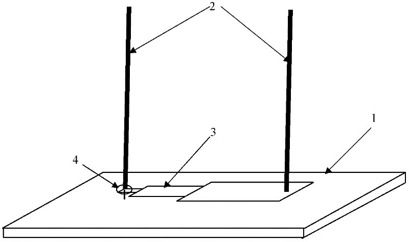
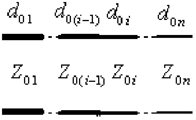
[0020] see figure 1 , an ultra-wideband miniaturized fractal antenna of the present invention is mainly composed of a ground plate 1, a double whip antenna 2, and an impedance transformation transmission line 3. The double-whip antenna 2 includes two metal posts vertically arranged on the ground plate 1; The above-mentioned impedance transformation transmission line 3 includes 2 or more metal strips with different widths, these metal strips are arranged from small to large according to their own widths, and are iteratively connected in the length direction of the metal strips, wherein the smallest width The metal strip is connected to one metal column of the double whip antenna 2, and the metal strip with the largest width is connected to another metal column of the double whip antenna 2. The double-whip antenna 2 and the impedance transformation transmission line 3 form an improved Hilbert fractal structure, which can effectively reduce the size of the antenna while maintain...


PUM


Abstract

The invention discloses an ultra wide band miniature fractal antenna which mainly comprises a ground plate, a twin-whip antenna and an impedance conversion transmission wire, wherein the twin-whip antenna comprises two metal columns vertically arranged on the ground plate; the impedance conversion transmission wire is arranged on the upper surface of the ground plate and is embedded between two metal columns of the twin-whip antenna; the impedance conversion transmission wire comprises at least two metal strips with different widths, the metal strips are arranged according to the order of from small width to big width and connected in an iteration manner in the length direction of the metal strips, wherein the metal strip with minimum width is connected with one metal column of the twin-whip antenna and the metal strip with maximum width is connected with the other metal column of the twin-whip antenna. The ultra wide band miniature fractal antenna can keep wider frequency band, higher radiation efficiency and better directional diagram characteristics while the size of the antenna is effectively reduced.

Description

technical field [0001] The invention relates to an antenna device, in particular to an ultra-wideband miniaturized fractal antenna. Background technique [0002] At present, quarter-wavelength monopoles, electrically small antennas, or conventional Hilbert fractal structures are often used to complete the design of short-wave or ultra-short-wave antennas. However, the above-mentioned design schemes have certain deficiencies: if a quarter-wavelength monopole is used to design a short-wave or ultra-short-wave antenna, since the length of the antenna is inversely proportional to the operating frequency, when the designed antenna needs to have a lower operating frequency , the length of the antenna is longer, so the mobility, erectability and concealment of the antenna are relatively poor. Using an electrically small antenna to design a short-wave or ultra-short-wave antenna will greatly increase the Q value of the antenna, reduce the radiation efficiency of the antenna, and li...

Claims


Application Information

Patent Timeline
Patent Type & Authority Applications(China)
IPC IPC(8): H01Q9/34H01Q9/38
Inventor 李思敏曹卫平刘扬清高喜
Owner GUILIN UNIV OF ELECTRONIC TECH
Why Eureka
Try Eureka