
Electric connector

A technology for electrical connectors and junction boxes, which is applied in the direction of connection, fixed connection, and parts of connection devices, which can solve the problems of unqualified products and easy errors.

Active Publication Date: 2012-06-27
吉安市联基电子有限公司
View PDF6 Cites 0 Cited by
  • Summary
  • Abstract
  • Description
  • Claims
  • Application Information

AI Technical Summary

Problems solved by technology

[0003] In view of this, the present invention aims at the deficiencies existing in the prior art, and its main purpose is to provide an electrical connector, which can effectively solve the problem that existing connectors are prone to errors when connecting with cables, resulting in unqualified products

Method used


Image

  • Electric connector
  • Electric connector
  • Electric connector

Examples


Embodiment Construction

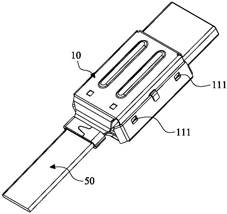
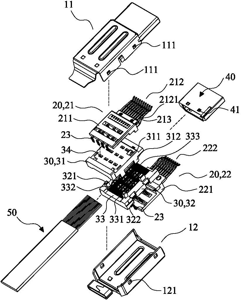
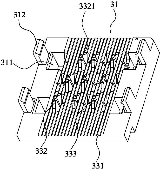
[0042] The present invention as Figure 1 to Figure 8 As shown, it includes a casing 10 , a terminal module 20 , a junction box 30 , an insulating body 40 and a cable 50 .

[0043] The housing 10 covers the exterior of the aforementioned terminal module 20, and includes an upper housing 11 and a lower housing 12. First buckle blocks 111 are respectively arranged on the outer walls of both sides of the upper housing 11, and on both sides of the lower housing 12. First buckle holes 121 matching the first buckle blocks 111 are respectively provided on the outer wall. When the upper housing 11 and the lower housing 12 are assembled, the first buckle blocks 111 are buckled in the first buckle holes 121 .

[0044] The terminal module 20 includes an upper terminal module 21 and a lower terminal module 22, wherein the upper terminal module 21 includes an upper terminal base 211 and an upper terminal group 212 embedded on the upper terminal base 211, and the lower terminal module 22 in...


PUM


Abstract

The invention discloses an electric connector. The electric connector comprises a shell, a terminal group, an insulation body and a flat cable. A branch box is arranged between the terminal group and the flat cable; the branch box comprises an upper branch box and a lower branch box; the flat cable is clamped between the upper branch box and the lower branch box; a bump which can be used for leading the piercing positions of the guide lines in the flat cable to be raised is arranged on one face of two clamp faces that the upper branch box and the lower branch box are fitted; a groove which is matched with a bump structure is arranged on the other clamp face; through holes are arranged at the raised part of each guide line in the flat cable corresponding to the branch box; a piercing part is arranged on each electric conduction terminal of the terminal group; and the piercing part penetrates through the through hole to pierce the flat cable to be connected with the flat cable, thereby the structure can be used for leading the adjacent lines to be staggered and branched in a certain order, which is beneficial for the electric conduction terminal to accurately pierce the flat cable, thus the reject ratio of the product can be effectively reduced, wherein the reject ratio is generated by that the electric conduction terminal slantly pierces; and the connector and the flat cable are conveniently assembled, thus the processing efficiency of the product is improved.

Description

technical field [0001] The present invention relates to the technical field of electrical connectors, in particular to an electrical connector. Background technique [0002] A variety of electronic products, such as the transmission of signals and currents between the main board of the computer and the DVD player and the peripheral systems of the computer, mostly rely on the use of wires or flat cables with connectors, and the flat cables are responsible for the transmission of most signals. The cable is made by paralleling many wires and then covering them with insulating materials. In the past, the cable connectors used in the cable can be roughly divided into three parts: the shell, the terminal group and the insulating body. Most of the time, the shell and the insulating body are combined to form a space, and then the cable is inserted into the space, and the conductive terminal in the terminal group is pierced through the outer skin of the cable by means of tools to ma...

Claims


Application Information

Patent Timeline
Patent Type & Authority Applications(China)
IPC IPC(8): H01R13/502H01R12/59
Inventor 洪明章林聪贤王钰陶武松
Owner 吉安市联基电子有限公司
Learn More