Vertebral arch pedicle screw system capable of being embedded with minimal invasion

A pedicle screw and placement technology, applied in the direction of internal fixator, internal bone synthesis, fixer, etc., can solve the problem of high difficulty of fixation rod, achieve the effect of saving operation time, convenient loading and unloading, and improving operation quality

Inactive Publication Date: 2012-07-04
陈远明
View PDF3 Cites 2 Cited by
  • Summary
  • Abstract
  • Description
  • Claims
  • Application Information

AI Technical Summary

Problems solved by technology

The traditional nail implantation process adopts open surgery, during which the fixation rod is inserted into the U-shaped groove from the end of the nail seat; in addition, the minimally invasive (percutaneous) method is also used under the X-ray perspective of the C-arm For implanting nails, the fixing rod of this surgical method needs to pass through the subcutaneous tunnel first, and then pene

Method used


Image

  • Vertebral arch pedicle screw system capable of being embedded with minimal invasion
  • Vertebral arch pedicle screw system capable of being embedded with minimal invasion
  • Vertebral arch pedicle screw system capable of being embedded with minimal invasion

Examples


Example Embodiment

[0020] Example 1

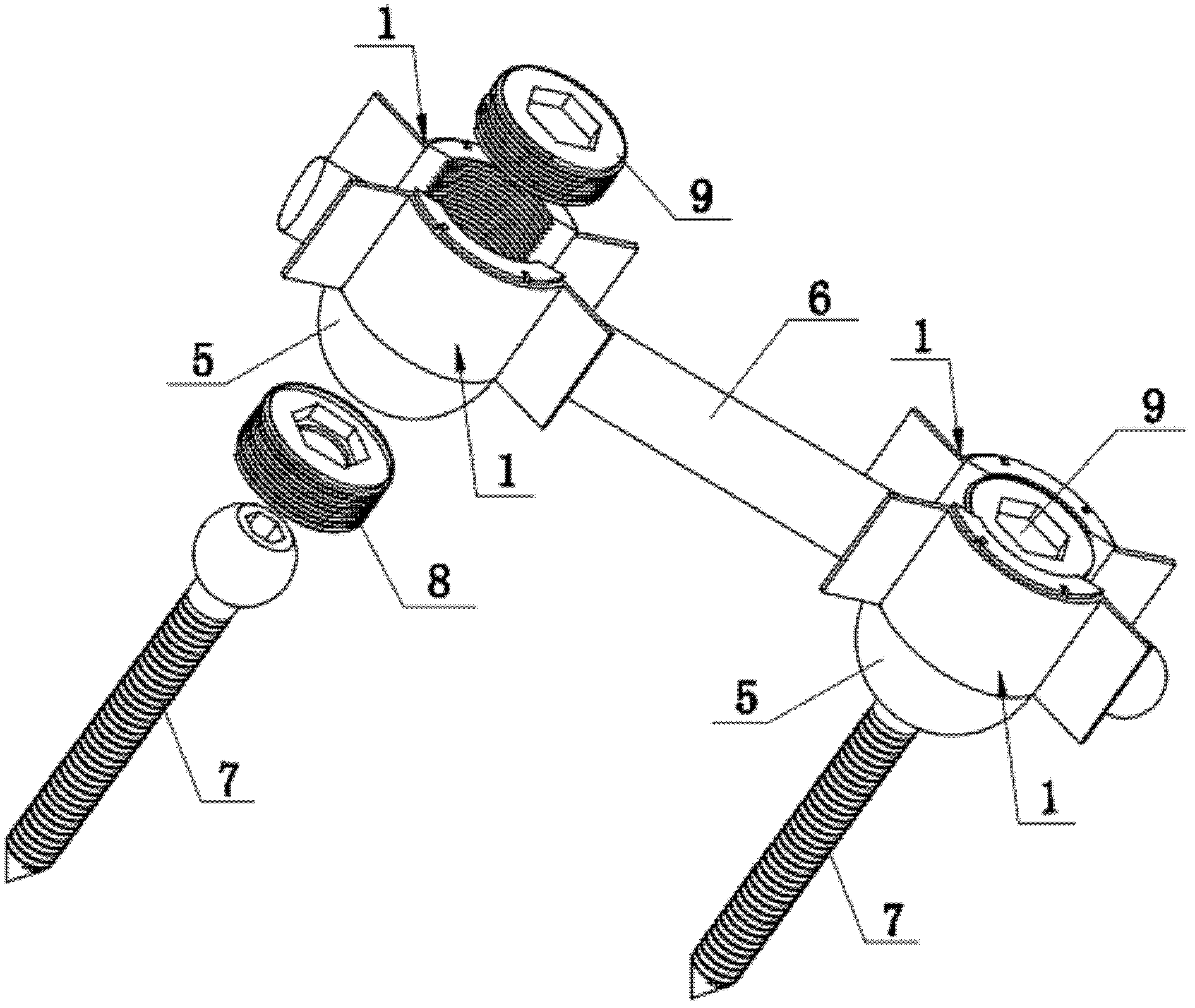
[0021] see figure 1 , the minimally invasive implantable rod pedicle screw system of this embodiment is a universal screw rod pedicle screw system, the universal pedicle screw system is composed of two screw assemblies and a fixation rod 6, Wherein, each screw assembly is composed of a nail seat 5, a pedicle screw 7, a ball head pressure block 8 and a screw plug 9. The cross section of the nail seat 5 is circular, and the center is provided with an axial The through hole of the pedicle screw 7, the lower part of the through hole is a hemispherical socket, and the upper part is a cylinder with an internal thread on the inner wall. The nail cap of the pedicle screw 7 is spherical, and it is matched with the nail when installed. In the hemispherical socket of the seat 5, the lower end of the ball head 8 is provided with a hemispherical socket that matches the spherical cap of the pedicle screw 7, and the ball head 8 is screwed to the screw seat 5. In the hole...

Example Embodiment

[0024] Example 2

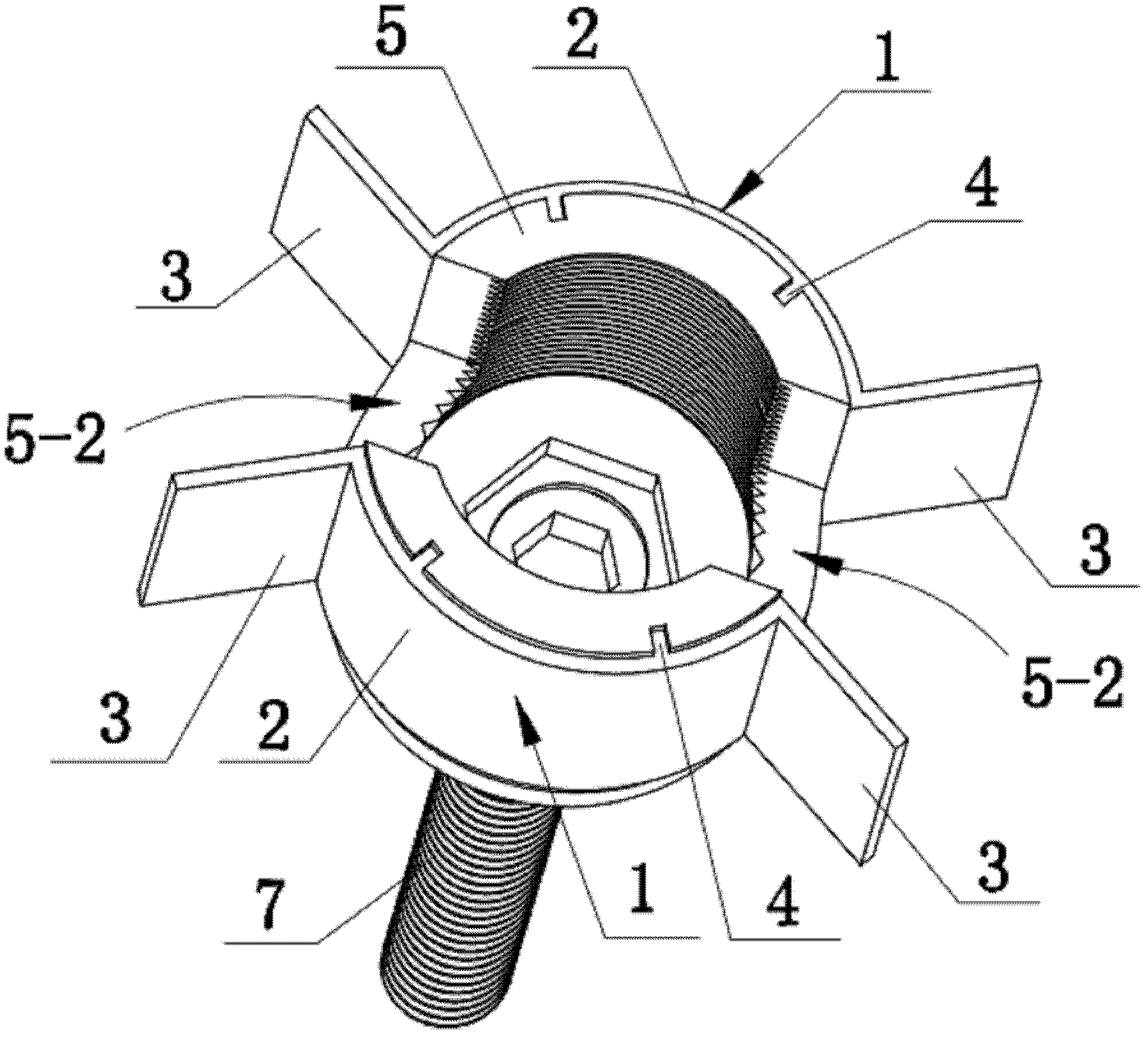
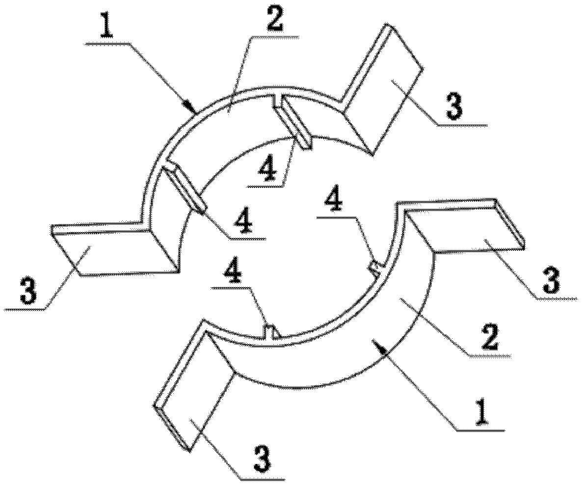
[0025] see Figure 7 and Figure 8 , The difference between this embodiment and Embodiment 1 is that the number of screw assemblies in this example is three, and the guide wings 3 at both ends of the arc plate 2 on the half guide 1 are arcs folded backwards Shape, that is, the orientation of the arc guide wing 3 arch is opposite to that of the arc plate 2 arch, so that the opening of the bell mouth formed by the two guide wings 3 is larger, which is more conducive to guiding the insertion of the fixing rod 6. In addition, the protrusions 4 provided on the circular arc plate 2 are changed from the continuous strip shape of the embodiment 1 to two discontinuous distribution bosses, and these two bosses are respectively arranged on the arc plate 2 the upper and lower edges of the .

[0026] Embodiments other than the above in this embodiment are the same as in Embodiment 1.


PUM


Abstract

The invention discloses a vertebral arch pedicle screw system capable of being embedded with minimal invasion, which comprises at least two screw seats (5) with round section. Each screw seat (5) is provided with a guider composed of two half guiders (1) which are symmetrically arranged on the outer walls of two sides of a U-shaped groove (5-2) on the screw seat (5), the middle of each half guider (1) is an arc plate (2) identical with the outer wall of the screw seat (5), the arc length of the arc plate is equal to the arc length on lateral outer wall of the U-shaped groove (5-2). Guide wings (3) are positioned at two ends of the arc plate (3), the end of the arc plate (2) in the middle of each half guider extends towards the outer side of the arc plate (2) to form the guide wing (3), two protrusions (4) parallel to the generatrix of the arc plate (2) are arranged on the inner wall of the arc plate (2) of each half guider (1), and location grooves (5-1) for the protrusions (4) to be inserted into are respectively and correspondingly positioned on the outer walls of two sides of the U-shaped groove (5-2) of each screw seat (5).

Description

technical field [0001] The invention relates to a medical surgical instrument, in particular to a spinal internal fixer, which is suitable for minimally invasive surgery of spinal internal fixation. Background technique [0002] Segmental instability of the spine, fracture fragments, or displacement of intervertebral disc tissue caused by lumbar fractures can compress the dural sac or nerve roots, causing neurological symptoms. Patients with neurological symptoms or severe fracture compression often require surgical treatment. The purpose of surgical treatment is to stabilize the spine, restore the height of the vertebral body, decompress the spinal canal, and reduce the compression on the nerves. The current classic operation method is to use the rod-rod pedicle screw system for strong internal fixation through the posterior pedicle. , a fixing rod and a screw plug, wherein the pedicle screw is set at one end of the screw seat, and the screw rod is set in the U-shaped gro...

Claims


Application Information

Patent Timeline
IPC IPC(8): A61B17/70
Inventor 陈远明
Owner 陈远明
Why Eureka
Try Eureka