
Steel rail switch twisting device

A processing device and track technology, which is applied in the field of radial torsion processing devices, can solve the problems of high manufacturing cost, low final angle and precision, unobtainable rail torsion angle, etc., and achieve the effect of reducing costs and realizing controllability

Inactive Publication Date: 2012-07-04
JIANGNAN UNIV
View PDF6 Cites 16 Cited by
  • Summary
  • Abstract
  • Description
  • Claims
  • Application Information

AI Technical Summary

Problems solved by technology

[0003] (1) The design and manufacture of the mold can only be processed according to one type of rail, and multiple sets of molds are required for the processing of various types of rails. The manufacturing cost of the mold is expensive and the design is complicated
[0004] (2) When designing the mold, it is difficult to accurately obtain the springback characteristics of the rail to be processed. In this way, the required torsion angle of the rail cannot be obtained, which makes the design and manufacture of the mold difficult
In addition, for the same type of rail, due to different batches, parameters such as hardness and elasticity are different, it is difficult to change the actual torsion angle at will to adapt to the springback of the rail, so that the final angle and accuracy of the rail after torsion are not high
[0005] (3) During the working process, the torsion angle cannot be displayed
[0006] (4) The wear of the mold, hot pressing processing and dimensional accuracy will also affect the improvement of the torsion accuracy of the rail

Method used


Image

  • Steel rail switch twisting device
  • Steel rail switch twisting device
  • Steel rail switch twisting device

Examples


Embodiment Construction

[0021] The specific implementation manner of the present invention will be described below in conjunction with the accompanying drawings.

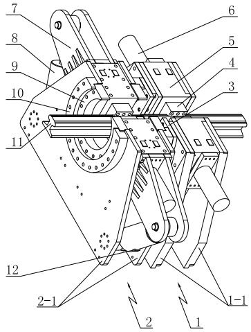
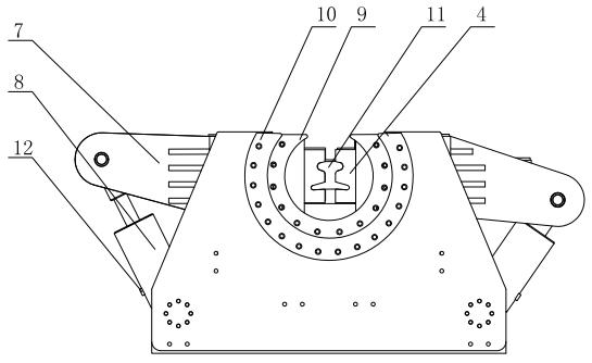
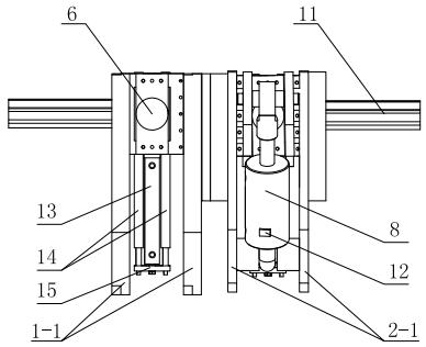
[0022] Such as Figure 1 to Figure 4 As shown, the present invention includes a first unit body 1 and a second unit body 2, the first unit body 1 and the second unit body 2 are fixedly connected by an intermediate connecting plate 3, so that the first unit body 1 and the second unit body The two unit bodies 2 are connected as a whole. The first unit body 1 and the second unit body 2 respectively comprise two substrates 1-1 and 2-1 spaced apart from each other, and the substrates are arranged in parallel with each other, and the substrates 1-1 and 2-1 are trapezoidal substrates; The installation block 5 is installed symmetrically between the two base plates 1-1 of the unit body 1, and a clamp sliding channel and a mounting hole for the locking bolt to pass are opened in the mounting block 5, and the clamp 4 and the clamp are installed in t...


PUM


Abstract

The invention discloses a steel rail switch twisting device. A first unit body and a second unit body are fixedly connected by a middle connecting plate into a whole; the first unit body and the second unit body respectively comprise two separated substrates, installing blocks are symmetrically mounted between the two substrates of the first unit body, a fixture sliding channel and a plug pin hole are formed in each installing block, a fixture is mounted in the fixture sliding channel, one ends of the left fixture and the right fixture are respectively fixedly connected with a piston rod of a clamping oil cylinder; a lock mechanism is mounted on the bottom of each installing block; the second unit body has the same structure with that of the first unit body, an inner flange and an outer flange are mounted on the substrate of the second unit body, the outer flange is fixedly connected with the outer wall of the substrate, the outer flange is supported against the outer circular face of the inner flange, the inner flange is fixedly connected with the outer walls of the installing blocks; the installing blocks are fixedly connected with one end of a twisting arm, the other end of the twisting arm is hinged with a twisting oil cylinder, a sensor is mounted on the twisting oil cylinder, and the other end of the twisting oil cylinder is hinged between the two substrates of the second unit body. The steel rail switch twisting device realizes controllability of the processing angle of a steel rail.

Description

technical field [0001] The invention relates to steel track fork processing equipment, in particular to a controllable radial torsion processing device for steel rails. Background technique [0002] A turnout is a line connection device that enables locomotives to transfer from one lane to another, and is usually laid at stations and marshalling yards. The processing quality of turnout rail is the basis of safe railway transportation. The production enterprises of turnout rails in my country, such as Baoji Bridge Factory, Zhuzhou Bridge Factory, Zibo Engineering Section, etc., all use the method of cold pressing and torsion processing of large-scale presses when processing steel rails. The principle is to use special molds to move the press up and down. , converted to torsion processing of rails. However, this processing method has the following disadvantages: [0003] (1) The design and manufacture of the mold can only be processed according to one type of rail, and multi...

Claims


Application Information

Patent Timeline
IPC IPC(8): B21D11/14
Inventor 孙明刘静
Owner JIANGNAN UNIV
Learn More