Bracket of machine tool

A technology of machine tools and outriggers, which is applied in the direction of metal processing machinery parts, large fixed members, metal processing equipment, etc., can solve the problems such as difficult to decompose the driving force, achieve good support effect, reduce the risk of machine tool rollover, and quickly fold and store Effect

Inactive Publication Date: 2012-07-04
QINGDAO D& D ELECTRO MECHANICAL TECH
View PDF6 Cites 3 Cited by
  • Summary
  • Abstract
  • Description
  • Claims
  • Application Information

AI Technical Summary

Problems solved by technology

[0004] There is also a deficiency in the prior art. When the operator needs to apply a lateral thrust in the process of using the machine tool, for example, when sawing wood horizontally, the machine support frame and the machine placed on it will be difficult due to the high center of gravity. Decompose the driving force, thereby increasing the possibility of rollover, which is very dangerous for the machine tool and the operator in the working state

Method used


Image

  • Bracket of machine tool
  • Bracket of machine tool
  • Bracket of machine tool

Examples


Embodiment Construction

[0071] The following examples are used to illustrate the present invention, but are not intended to limit the scope of the present invention.

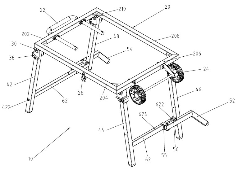
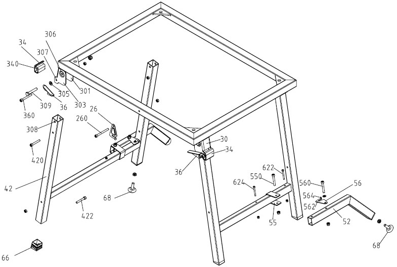
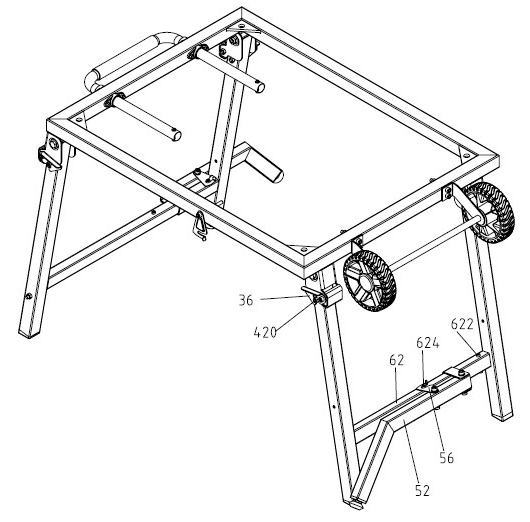
[0072] see figure 1 Shown is a machine tool support 10 of a preferred embodiment of the present invention, has a support platform 20 and four legs 42, 44, 46, 48, each leg is pivoted by a pivot bolt 309 and a connecting plate 30 Connected on the support platform 20, reinforcing beams 62 are respectively arranged between the legs 42, 48 and between the legs 44, 46, and the auxiliary legs 52, 54 are pivotally connected to the reinforcing beams 62 through the sleeve plate 55, and the auxiliary legs The legs are used to effectively expand the contact area.

[0073] The support platform 20 is a frame body with a left side frame 202, a front side frame 204, a right side frame 206 and a rear side frame 208, wherein the left side frame 202 is fixed with a U-shaped handle 22 for users to hold, and the right side frame A pair of casters 24 are...


PUM


Abstract

The invention discloses a bracket of a machine tool. The bracket comprises a supporting platform, a plurality of supporting legs and a plurality of auxiliary supporting legs, wherein the supporting legs are pivotally connected with the supporting platform; the auxiliary supporting legs are pivotally connected to the supporting legs for effectively increasing the contact area; and the supporting legs and the auxiliary supporting legs are all foldable. By using the bracket of the machine tool provided by the invention, the supporting effect is excellent, and simple and stable storage and expansion modes can be provided.

Description

technical field [0001] The invention relates to a machine tool support, in particular to a machine tool support for stably supporting a machine tool and capable of quick storage. Background technique [0002] Chinese patent CN2826621Y discloses a support frame for a machine, which provides a support frame on which the machine can be placed. Using the support frame, the machine can have a predetermined height, which is convenient for the user to operate the machine in a standing posture. The support frame has several load bearing parts, several legs, several connecting rods and several fixed components, and the parts are mainly engaged with each other, and the jointed components themselves have embedded parts or grooves with different shapes. [0003] However, when the user needs to assemble and store the above-mentioned support frame for the machine, each component needs to be installed and disassembled one by one, which makes the storage process cumbersome, and the disassem...

Claims


Application Information

Patent Timeline
Patent Type & Authority Applications(China)
IPC IPC(8): B23Q1/01
Inventor 张永升荆旭光吴院兵
Owner QINGDAO D& D ELECTRO MECHANICAL TECH
Why Eureka
Try Eureka