
Thermal displacement compensation method and thermal displacement compensation device for machine tool

A compensation method and a compensation device technology, which are applied to feeding devices, automatic control devices, metal processing machinery parts, etc., can solve the problem of low thermal displacement estimation accuracy, etc.

Inactive Publication Date: 2012-07-04
FANUC LTD
View PDF9 Cites 28 Cited by
  • Summary
  • Abstract
  • Description
  • Claims
  • Application Information

AI Technical Summary

Problems solved by technology

[0014] In the technology disclosed in the above-mentioned patent documents, when the variation of the compensation amount is large, instead of using the thermal displacement measured in advance by using an approximate formula, the thermal displacement measured by the sensor is used as the compensation amount, and it is not based on the result measured by the sensor. Since the coefficients of the calculation formula used to estimate the thermal displacement are corrected, the results measured by the sensor are not reflected in the subsequent estimation of the thermal displacement, and the estimation accuracy of the thermal displacement is not high.

Method used

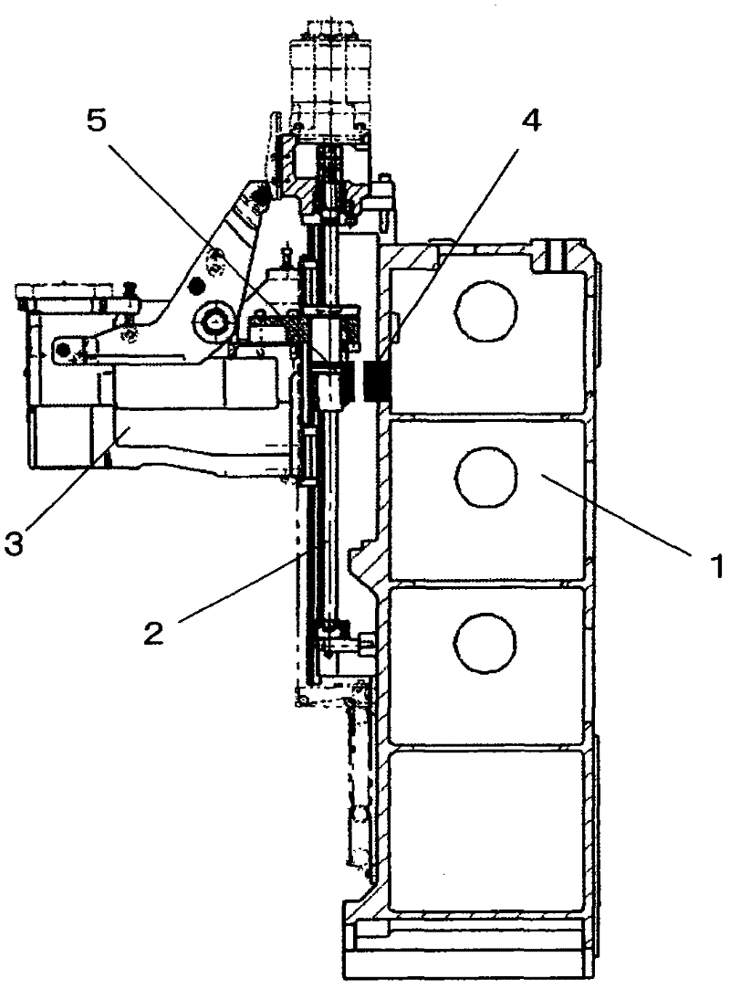
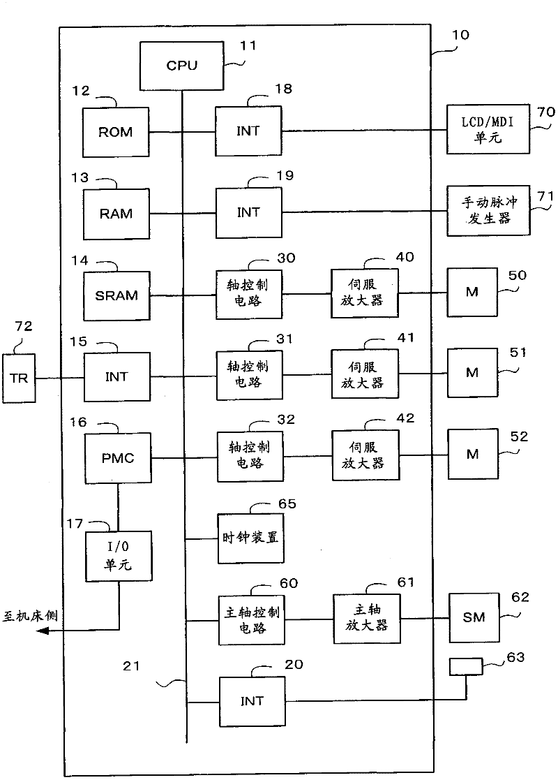

Image

  • Thermal displacement compensation method and thermal displacement compensation device for machine tool
  • Thermal displacement compensation method and thermal displacement compensation device for machine tool
  • Thermal displacement compensation method and thermal displacement compensation device for machine tool

Examples


no. 1 approach

[0056] (b1) Setting of the interval for estimation and compensation of the thermal displacement of the feed axis

[0057] First, the calculation and compensation of the thermal displacement of the feed shaft will be described. The method of calculating (estimating) the amount of thermal displacement described here is the same as the method disclosed in Japanese Patent Application Laid-Open No. 2002-18677.

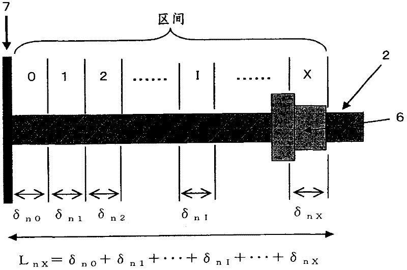
[0058] First, if image 3 As shown in , the entire length (stroke) of the feed screw 2 constituting the feed shaft is divided into a plurality of sections. Here, the total length of the feed screw 2 refers to one end surface of the fixed bearing supporting one end of the feed screw (in detail, the end surface on the side of the nut 6 of the fixed bearing, and this end surface is defined as the reference position 7 ) to an end surface of the nut 6 when the nut 6 engaged with the feed screw 2 moves on the feed screw 2 and moves to the position farthest from the fixed bearin...


PUM


Abstract

The invention provides a thermal displacement compensation method for a machine tool and a thermal displacement compensation device. In the thermal displacement compensation method for the machine tool, in which a feed shaft thermal displacement amount is obtained and an amount which cancels the obtained feed shaft thermal displacement amount is added as a thermal displacement compensation amount to a position command for a feed axis, a position where a signal is first output by a position sensor for detecting the position of a movable part of the machine tool is first stored as an initial position. Then, the position where the signal is output by the position sensor is detected, and the thermal displacement compensation amount is modified according to a compensation error, which is the difference between the detected position (actual position) and the initial position.

Description

technical field [0001] The invention relates to a thermal displacement compensation method and a thermal displacement compensation device in a machine tool. Background technique [0002] In a machine tool, the feed screw and the main shaft are driven by a motor, so due to the heat generated by the motor, the frictional heat caused by the rotation of the bearing, and the frictional heat of the meshing portion of the ball screw and ball nut of the feed screw, the main shaft or the feed screw Expansion, displacement of mechanical position. That is, a deviation occurs in the relative positional relationship between the workpiece to be positioned and the tool. Such heat-induced displacement of the mechanical position becomes a problem in the case of high-precision machining. [0003] In order to eliminate the displacement of the mechanical position due to heat, the technique of compensating the thermal displacement simply and at low cost without using a temperature sensor has b...

Claims


Application Information

Patent Timeline
Patent Type & Authority Applications(China)
IPC IPC(8): B23Q15/18
CPCG05B19/404G05B2219/49207G05B2219/49212
Inventor 前川进远藤高弘
Owner FANUC LTD
Learn More