Liquid retaining bag

A liquid and stop-flow technology, applied in the field of liquid container structure, can solve the problems of pollution, waste, lack of stop-flow function, etc., and achieve the effects of convenient use and low manufacturing cost

Active Publication Date: 2012-07-04
KUNSHAN AIRBAG PACKING CORP
View PDF6 Cites 2 Cited by
  • Summary
  • Abstract
  • Description
  • Claims
  • Application Information

AI Technical Summary

Problems solved by technology

However, since this kind of flexible packaging bag structure cannot be sealed again, it does not have the function of stopping flow. Therefore, after tearing to form an opening, it must be stored carefully. Once it is dumped, the liquid in the flexible packaging bag will leak through the opening. Will cause pollution or waste, quite inconvenient

Method used


Image

  • Liquid retaining bag
  • Liquid retaining bag
  • Liquid retaining bag

Examples


no. 2 example

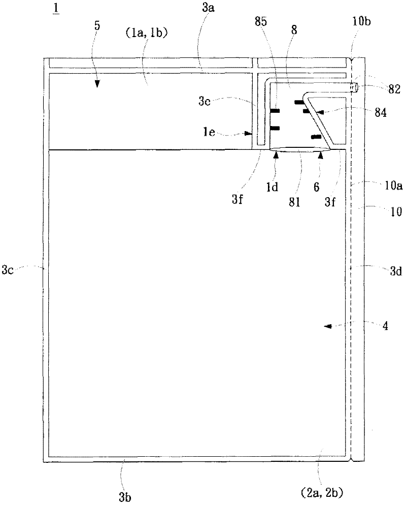
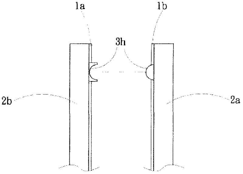
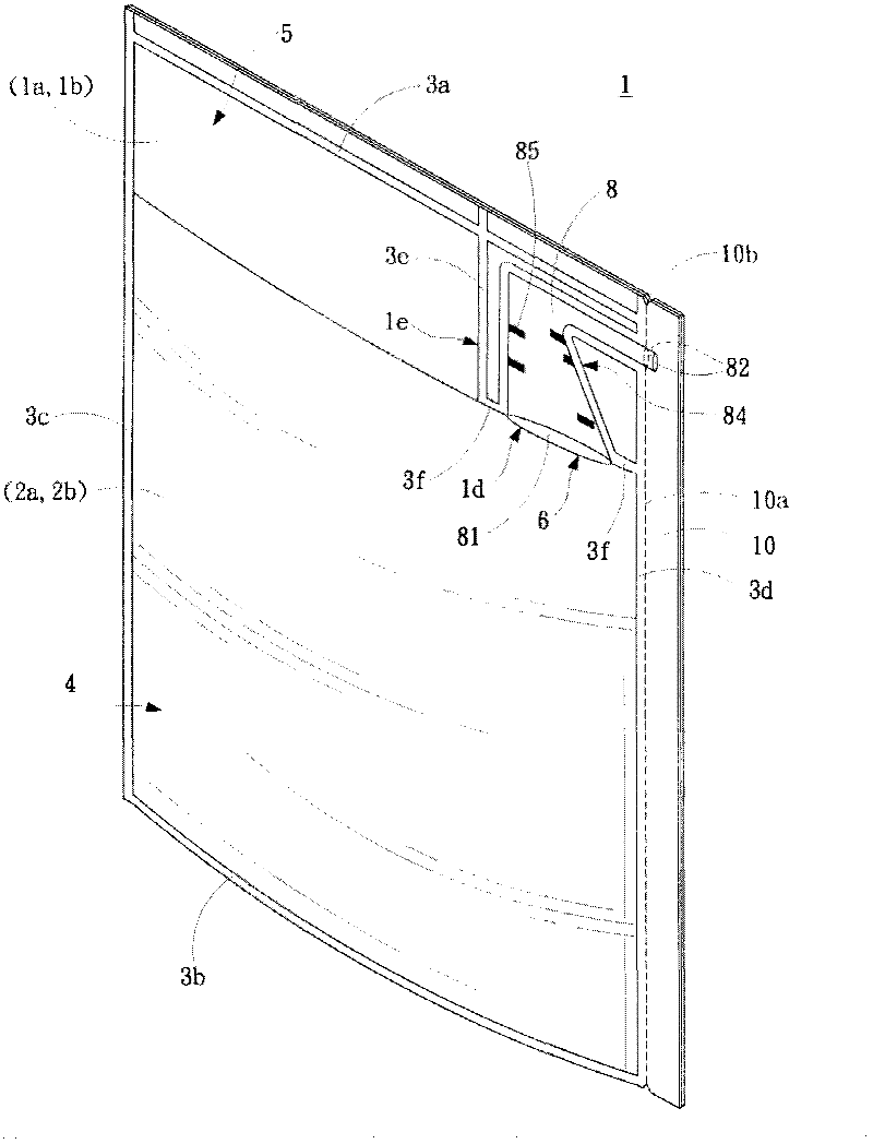
[0077] Figure 3A shows the second embodiment of the present invention: the inner membrane vertical stop structure

[0078] Two narrower inner films are placed vertically on one side of the two outer films, and the upper sections of the four films are simultaneously heat-sealed. The heat-sealing lines 3b, 3c, 3d, and 3f form a liquid-containing bag 1, and The bag body is divided into: filling area 5, discharging area 8, storage area 4, and heat sealing line 3e. A discharge channel is formed in the discharge area and includes at least an inlet 81, a curved portion 84 and an outlet 82. When the inlet 81 and the outlet 82 are heat-sealed, a baffle is applied to the inner surfaces of the two inner films 1a and 1b or a heat-resistant sealing material is pre-coated so that the inner surfaces of the two inner films 1a and 1b are not adhered to the inner surfaces during heat sealing. However, the two inner films 1a, 1b and the two outer films 2a, 2b opposed to each other are heat-sealed t...


PUM


Abstract

A liquid retaining bag comprises two outer membranes, two inner membranes, a storage area, a discharging way, bent portions, inlets, an outlet and a tearing part, wherein the bent portions, the inlets and the outlet are arranged in the discharging way. The storage area is formed by connecting the two outer membranes by means of heat sealing, the two inner membranes are positioned between the two outer membranes, the two outer membranes are connected with the inner outer membranes by means of heat sealing to form the discharging way or the discharging way is connected with the inner membranes by means of heat sealing to form between the two inner membranes, the inlets and the outlet are formed by means of heat sealing of the inner faces of the two inner membranes in a disconnected manner, the tearing part is positioned on the lateral sides of the inner membranes and the outer membranes, and the tearing part is exposed outside the outlet of the discharging way after being separated from the two inner membranes. When the two outer membranes is extruded by external force, the outer membranes are extruded by liquid to be opened outward so that the inlets of the discharging way can be opened automatically, the liquid flows into the bent portions of the discharging way through the inlets and flows out through the outlet. When the external force is relieved, the liquid flows back to the storage area through the bent portions, reaction suction force is generated during dropping, the two inner membranes in the bent portions are mutually attached due to the suction force to close the discharging way, and the liquid stops flowing and cannot flow out of the bag.

Description

Technical field [0001] The invention relates to a liquid container structure, in particular to a liquid stop bag. Background technique [0002] Commercially available beverages or liquid foods and cleaning products mainly use canned plastic PET bottles with caps as containers. At present, the common PET bottles have an integrally formed bottle body, which can accommodate In the liquid space, a bottle opening is provided above the bottle body for pouring liquid or inserting a straw to suck drinking. There are hundreds of billions of Pote bottle containers used in the world every year. Disposal has a huge impact on environmental protection, especially the transportation of empty bottles, waste recycling and other issues, which are quite inconvenient for subsequent disposal. [0003] In response to environmental issues, there is a flexible packaging bag structure that can contain liquids. When the user wants to eat or use the liquid, he tears the flexible packaging bag to form an op...

Claims


Application Information

Patent Timeline
Patent Type & Authority Applications(China)
IPC IPC(8): B65D30/14B65D33/16B65D33/36
Inventor 简伯欣廖耀鑫尹静雯
Owner KUNSHAN AIRBAG PACKING CORP
Why Eureka
Try Eureka