Reciprocating pneumatic water pump
A reciprocating and water pump technology, applied in the direction of pumps, piston pumps, machines/engines, etc., can solve problems such as the inability to obtain stable and continuous energy sources, the lack of deep development and utilization of new energy sources, and the lack of reliable energy storage methods. Simple, easy-to-manufacture effects
- Summary
- Abstract
- Description
- Claims
- Application Information
AI Technical Summary
Problems solved by technology
Method used
Image
Examples
Embodiment 1
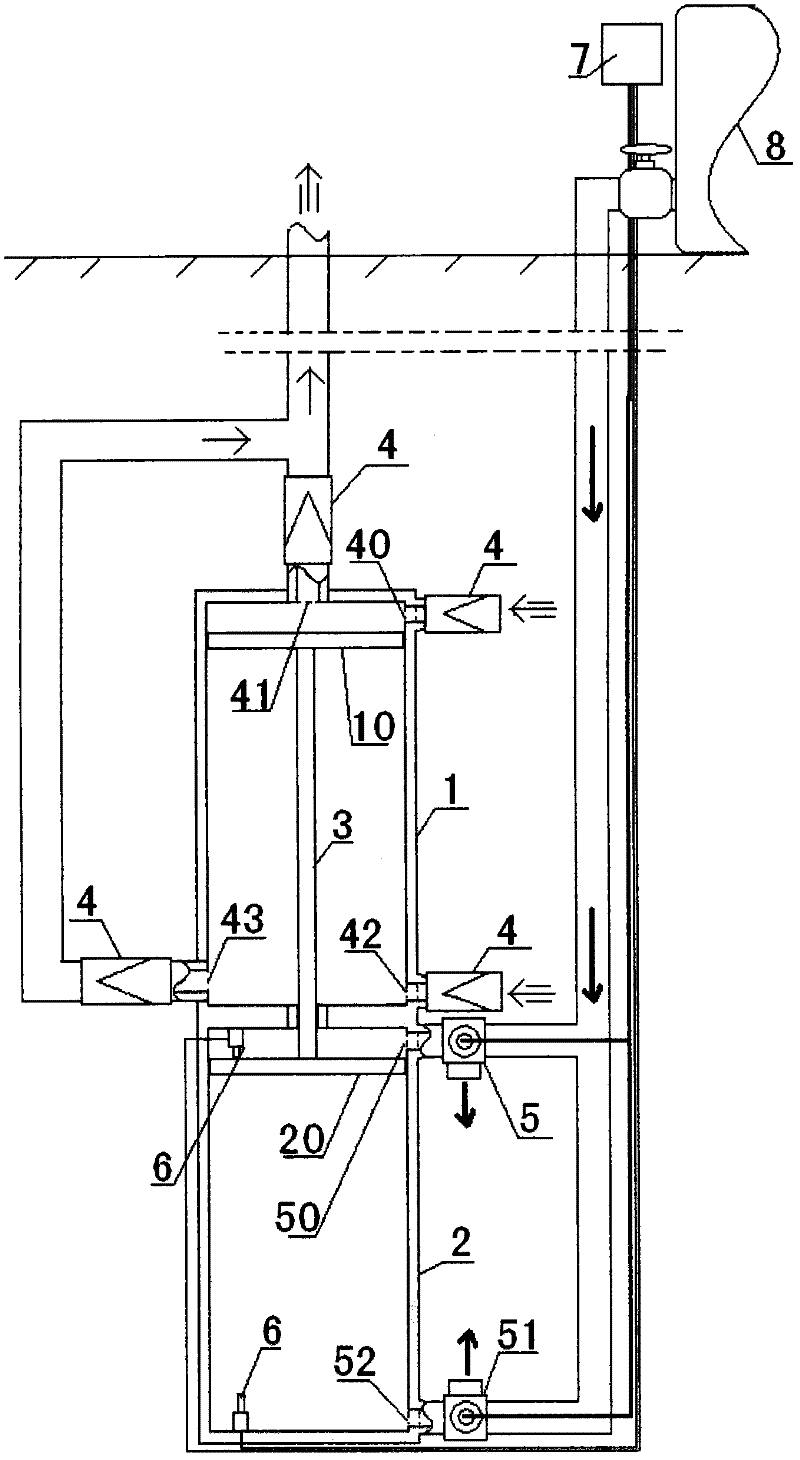
[0020] Embodiment one, such as figure 1 As shown, the reciprocating pneumatic water pump of the present invention uses a reciprocating piston air pump to generate reciprocating power, and the reciprocating power drives the reciprocating piston water pump; the reciprocating piston air pump is equipped with an air valve or an air actuator that matches the rhythm of the pneumatic piston .
[0021] More specifically, it includes a water pump chamber 1 and a pneumatic chamber 2 that are symmetrically distributed up and down. The water pump chamber 1 and the pneumatic chamber 2 are equipped with a synchronously operating water pump piston 10 and a pneumatic piston 20 respectively. seal) and airtight (air seal) through the main shaft 3 of the water pump chamber 1 and the wall 21 of the pneumatic chamber 2; The upper water outlet 41, the water pump chamber 1 is formed with the lower water inlet 42 and the lower water outlet 43 respectively equipped with the check valve 4 below the bo...
Embodiment 2
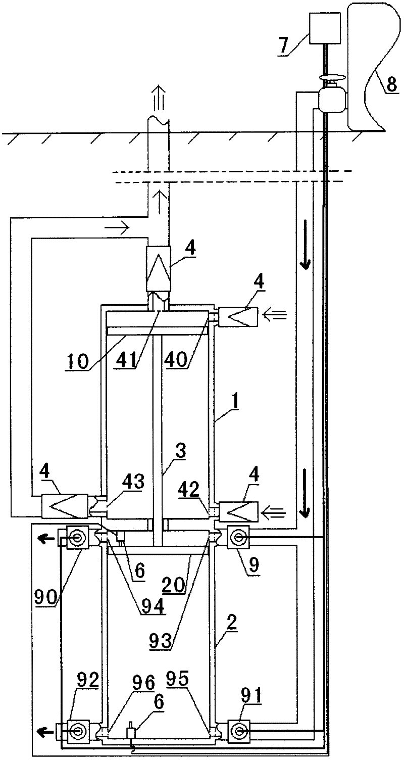
[0024] Embodiment two, such as figure 2 As shown, the reciprocating pneumatic water pump of the present invention uses a reciprocating piston air pump to generate reciprocating power, and the reciprocating power drives the reciprocating piston water pump; the reciprocating piston air pump is equipped with an air valve or an air actuator that matches the rhythm of the pneumatic piston .
[0025] More specifically, it includes a water pump chamber 1 and a pneumatic chamber 2 that are symmetrically distributed up and down. The water pump chamber 1 and the pneumatic chamber 2 are equipped with a synchronously operating water pump piston 10 and a pneumatic piston 20 respectively. seal) and airtight (air seal) through the main shaft 3 of the water pump chamber 1 and the wall 21 of the pneumatic chamber 2; The upper water outlet 41, the water pump chamber 1 is equipped with a lower water inlet 42 and a lower water outlet 43 respectively equipped with a check valve 4 below the botto...
Embodiment 3
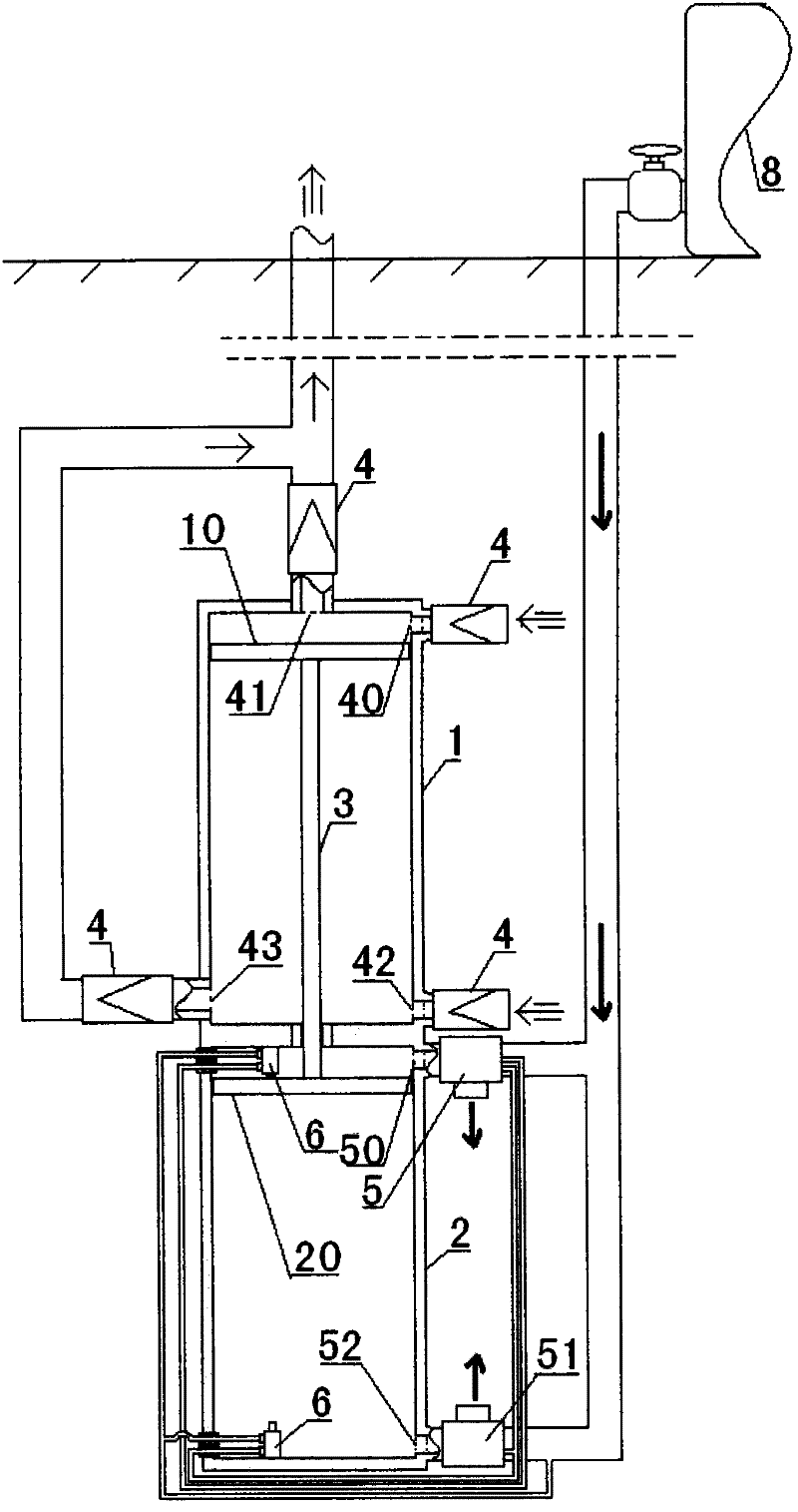
[0029] Embodiment three, such as image 3 As shown, the reciprocating pneumatic water pump of the present invention uses a reciprocating piston air pump to generate reciprocating power, and the reciprocating power drives the reciprocating piston water pump; the reciprocating piston air pump is equipped with an air valve or an air actuator that matches the rhythm of the pneumatic piston .
[0030] More specifically, it includes a water pump chamber 1 and a pneumatic chamber 2 that are symmetrically distributed up and down. The water pump chamber 1 and the pneumatic chamber 2 are equipped with a synchronously operating water pump piston 10 and a pneumatic piston 20 respectively. seal) and airtight (air seal) through the main shaft 3 of the water pump chamber 1 and the wall 21 of the pneumatic chamber 2; The upper water outlet 41, the water pump chamber 1 is formed with the lower water inlet 42 and the lower water outlet 43 respectively equipped with the check valve 4 below the ...
PUM
 Abstract
Description
Claims
Application Information
 - R&D
- Intellectual Property
- Life Sciences
- Materials
- Tech Scout
- Unparalleled Data Quality
- Higher Quality Content
- 60% Fewer Hallucinations
Browse by: Latest US Patents, China's latest patents, Technical Efficacy Thesaurus, Application Domain, Technology Topic, Popular Technical Reports.
© 2025 PatSnap. All rights reserved.Legal|Privacy policy|Modern Slavery Act Transparency Statement|Sitemap|About US| Contact US: help@patsnap.com


