vacuum pump

A technology of vacuum pump and air outlet, applied in the direction of pumps, pump components, variable capacity pump components, etc., can solve the problems of inability to adapt to use, affecting the vacuum degree of the vacuum pump, and reducing the volume, so as to achieve a small occupied space and improve installation efficiency. , the effect of saving installation time

Active Publication Date: 2015-11-25
XIAMEN CONJOIN ELECTRONICS TECH
View PDF7 Cites 0 Cited by
  • Summary
  • Abstract
  • Description
  • Claims
  • Application Information

AI Technical Summary

Problems solved by technology

[0004] 1. The umbrella check valve is inconvenient to install. When installing the umbrella check valve, the umbrella handle of the umbrella check valve is generally installed in the air outlet. In this way, the umbrella handle must be squeezed into the air outlet with the help of tools. , the installation efficiency is low, especially when the vacuum pump needs to be provided with more than two air outlets, the umbrella-shaped check valves are installed one by one, and the installation efficiency is lower;
[0005] 2. An umbrella-shaped one-way valve is installed in the air outlet. The umbrella-shaped one-way valve is affected by thermal expansion and contraction of temperature. When the temperature is low, its volume shrinks and cannot be well sealed with the air outlet, which affects the vacuum degree of the vacuum pump;
[0006] 3. Umbrella-shaped one-way valves are installed in the air outlet. When multiple umbrella-shaped one-way valves are installed in multiple air outlets, it takes up too much space. For micro vacuum pumps, it will inevitably affect the overall volume of the product, and more Even, the miniature vacuum pump cannot be adapted for use in related equipment due to its large size

Method used


Image

  • vacuum pump
  • vacuum pump

Examples


Embodiment Construction

[0037] The present invention will be described in detail below in conjunction with the accompanying drawings and specific embodiments.

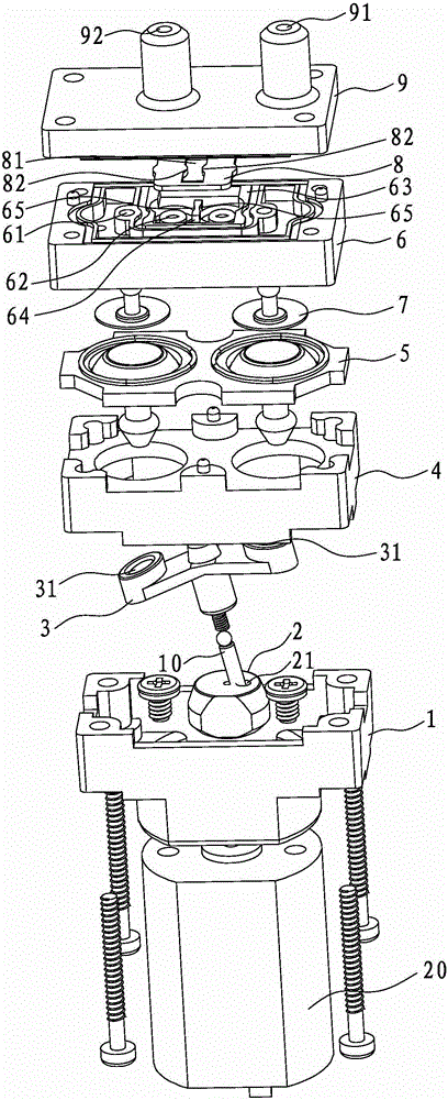
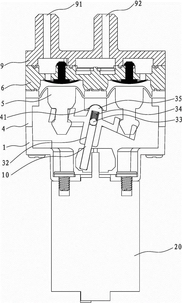
[0038] refer to figure 1 and figure 2 As shown, the vacuum pump disclosed by the present invention includes a housing 1, a cam 2, a curved rod 3, a support 4, an air bag 5, a valve seat 6, an umbrella-shaped one-way valve 7, a pressing piece 8, a top cover 9, and a connecting rod 10 And motor 20.

[0039] The motor 20 is installed in the casing 1 , the cam 2 is installed on the rotating shaft of the motor 20 , and the cam 2 is provided with an eccentric hole 21 .

[0040] The connecting rod 10 is placed in the eccentric hole 21 and connected with the curved rod 3 . A central shaft hole 32 can be set on the curved rod 3, and a spring 34 and a ball 33 are put into the shaft hole 32 successively. One end of the connecting rod 10 is inserted in the central shaft hole 32, and the other end is inserted in the eccentric hole 21 of the cam 2. Wh...


PUM


Abstract

The invention discloses a vacuum pump which comprises a motor, a casing, a cam, a connecting rod, a crank, a support seat, an airbag, an umbrella-shaped one-way valve, a pressing sheet, a valve seat and a top cover, wherein the motor is arranged in the casing; the cam is arranged on a rotating shaft of the motor and is provided with an eccentric hole; the connecting rod is arranged in the eccentric hole and is connected with the crank; the bottom of the airbag is arranged on the crank; the airbag is arranged on the support seat; the support seat is erected on the casing; the valve seat is arranged on the support seat; an air inlet hole and an air outlet hole are arranged in the valve seat and are separated by using a twig; the air inlet hole and the air outlet hole are opposite to the airbag in position; the umbrella-shaped one-way valve is arranged on the air inlet hole; the pressing sheet is pressed on the air outlet hole; the top cover is arranged on the valve seat; an air inlet and an air outlet are arranged in the top cover; the air inlet hole and the air inlet are communicated to form an air inlet channel; and the air outlet hole and the air outlet are communicated to form an air outlet channel. The vacuum pump disclosed by the invention is convenient to mount the pressing sheet, is better in vacuum degree and is smaller in size.

Description

technical field [0001] The invention relates to a vacuum pump, in particular to a miniature vacuum pump. Background technique [0002] In the prior art, a vacuum pump generally includes a motor, a housing, a cam, a connecting rod, a curved rod, a support, an air bag, an umbrella check valve, a valve seat and a top cover; the motor is installed in the housing, and the cam is installed in the motor. On the rotating shaft, an eccentric hole is set on the cam; the connecting rod is placed in the eccentric hole and connected with the curved rod; the bottom of the airbag is installed on the curved rod, the airbag is installed on the support, and the support is erected on the shell; the valve seat is installed On the support, an air inlet and an air outlet are arranged on the valve seat, and the air inlet and the air outlet are separated by wattles. The position of the air inlet and the air outlet is opposite to the air bag, and an umbrella-shaped single Directional valve; the top...

Claims


Application Information

Patent Timeline
Patent Type & Authority Patents(China)
IPC IPC(8): F04B37/14F04B45/067F04B39/00
Inventor 颜宏
Owner XIAMEN CONJOIN ELECTRONICS TECH
Why Eureka
Try Eureka