Compression refuse collector and hydraulic system thereof

A hydraulic system and hydraulic oil technology, which is applied in the hydraulic system field of compressed garbage trucks, can solve the problems of slow moving speed of the compression mechanism, large flow fluctuation, and confluence working conditions, etc., and achieve beautiful and concentrated appearance, stable operating flow, Effect of reducing pressure loss

Inactive Publication Date: 2012-07-04
ZOOMLION ENVIRONMENTAL IND CO LTD
View PDF8 Cites 28 Cited by
  • Summary
  • Abstract
  • Description
  • Claims
  • Application Information

AI Technical Summary

Problems solved by technology

Although this method can meet the requirements of the above two working conditions, there is an obvious disadvantage, that is, the hydraulic oil entering the system from the oil inlet P1 passes through the reversing valve connected with the lifting cylinder 8 and the valve connected with the turning cylinder 9. The middle position of the reversing valve passes through the oil passage d through the confluence unit 10 and then through the oil passage c to complete the confluence with the hydraulic oil entering the system from the oil inlet P2, which meets the compression operation conditions that the slide cylinder 6 and the scraper cylinder 7 operate in sequence , but the system becomes a confluence working condition when the operation of the bucket turning cylinder 9 is intermittent under linkage conditions, resulting in a time-divided and time-divided flow rate during the compression operation, a relatively large flow rate fluctuation, and a compression mechanism that moves at a speed that is sometimes fast and sometimes slow. not running smoothly

Method used


Image

  • Compression refuse collector and hydraulic system thereof
  • Compression refuse collector and hydraulic system thereof
  • Compression refuse collector and hydraulic system thereof

Examples


Embodiment Construction

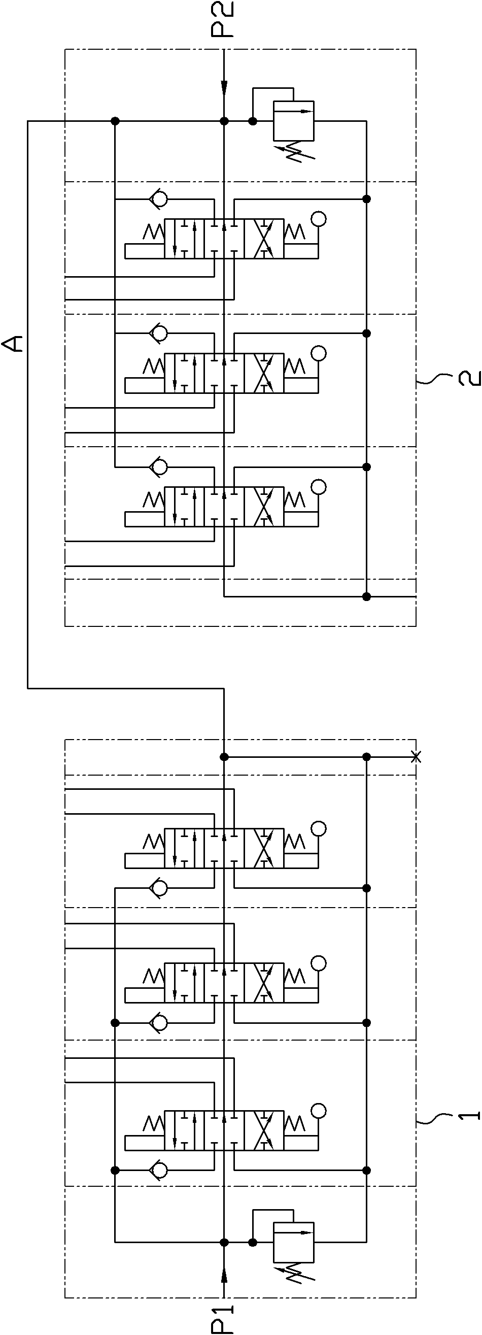
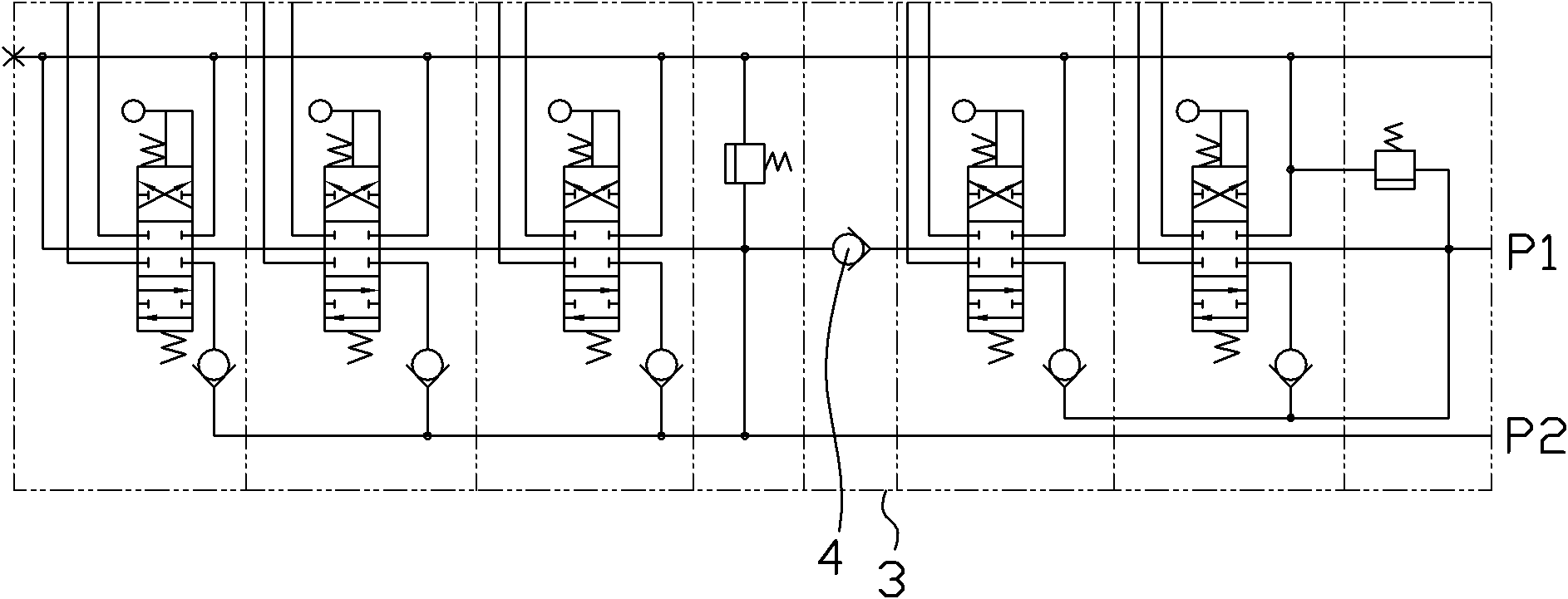
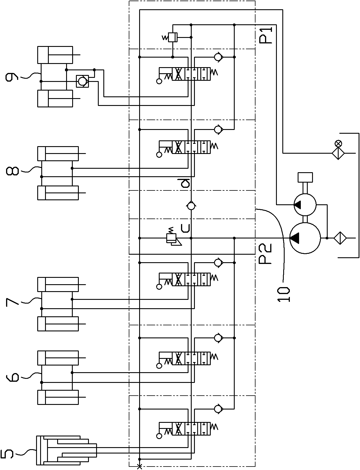
[0022] Figure 4 It is a schematic diagram of the principle of the hydraulic system of the compression garbage truck in the embodiment of the present invention. Please refer to Figure 4 , In this embodiment, the hydraulic system includes a main valve 20 , a double oil pump 30 , an oil tank 40 , a first oil cylinder system 50 , a second oil cylinder system 52 , and a total oil passage 60 . The dual oil pump 30 includes a first oil pump 32 and a second oil pump 34 . The oil tank 40 is connected with the double oil pump 30 , and the double oil pump 30 is connected with the main valve 20 . The main oil passage 60 includes a first oil inlet P1, a second oil inlet P2, a first oil return port T1, and a second oil return port T2. In this embodiment, the hydraulic oil in the main oil passage 60 passes through the first oil return port T2. Oil can be returned through the first oil return port T1, of course, oil can also be returned through the second oil return port T2 according to ...


PUM


Abstract

The invention provides a hydraulic system, which comprises a double-oil-pump, an main oil passage, a first valve set, a second valve set, a first cylinder system, a second cylinder system, a control unit and an oil return unit. The first valve set, the control unit, the oil return unit and the second valve set are connected through the main oil passage sequentially. The control unit comprises a multi-way reversing valve, and the oil return unit is communicated with an oil return port of the main oil passage and comprises an internal oil passage. The hydraulic system has a combination state and a linkage state. When in the combination state, hydraulic oil of a first oil pump flows through the first valve set and the control unit sequentially to enter the inside of the oil return unit through an oil port of the multi-way reversing valve of the control unit, and then combined with hydraulic oil of a second oil pump in the second valve set. When in the linkage state, the multi-way reversing valve of the control unit is located in the middle, the first valve set and the second valve set complete operation respectively. The invention further provides a compression refuse collector adopting the hydraulic system.

Description

technical field [0001] The invention relates to the field of hydraulic systems, in particular to a hydraulic system for compressing garbage trucks. Background technique [0002] Existing hydraulic systems generally use multi-way reversing valves for control. In order to reduce energy consumption and improve operating efficiency, current hydraulic systems mostly use double oil pumps as power sources. During the operation process, the flow control of the two oil pumps, For working conditions such as linkage (two pumps work independently and simultaneously), confluence, etc., the prior art has the following two methods. [0003] For the first method, see figure 1 , a group of multi-way directional control valves only controls one pressure oil source, if you want two pressure oil sources to merge, you must use two sets of multi-way directional control valves. This method uses the first group of valves 1 and the second group of valves 2 to control the hydraulic oil entering the...

Claims


Application Information

Patent Timeline
Patent Type & Authority Applications(China)
IPC IPC(8): F15B11/17F15B13/06B65F3/14
Inventor 刘臻树刘文革
Owner ZOOMLION ENVIRONMENTAL IND CO LTD
Why Eureka
Try Eureka