Heat-dissipating disk for LED (light-emitting diode) lamps

A technology of LED lamps and heat sinks, applied in the cooling/heating devices of lighting devices, lighting and heating equipment, components of lighting devices, etc., can solve the problem of not having internal heat dissipation performance, and achieve long service life and small size , improve the effect of integration

Inactive Publication Date: 2012-07-04
管惠良
View PDF0 Cites 0 Cited by
  • Summary
  • Abstract
  • Description
  • Claims
  • Application Information

AI Technical Summary

Problems solved by technology

However, the current heat sinks of LED lamps generally

Method used


Image

  • Heat-dissipating disk for LED (light-emitting diode) lamps
  • Heat-dissipating disk for LED (light-emitting diode) lamps
  • Heat-dissipating disk for LED (light-emitting diode) lamps

Examples


Example Embodiment

[0019] The specific embodiments of the present invention will be further described in detail below in conjunction with the accompanying drawings. For those skilled in the art, the above and other objectives, features and advantages of the present invention will be apparent from the detailed description of the present invention.

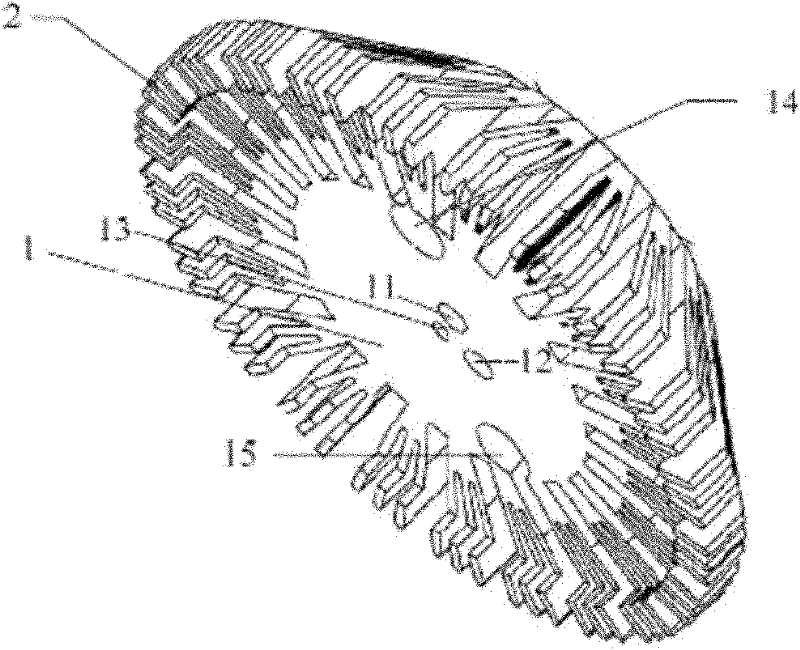
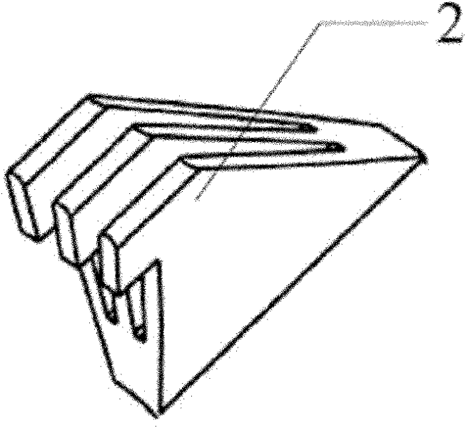
[0020] figure 1 Shown is a structural diagram of a heat dissipation plate according to an embodiment of the present invention, which includes a base 1 and a plurality of heat dissipation wings 2. The base is located in the center and plays the role of supporting the cooling wing. The shape of the base may be cylindrical, square, cone, prismatic, or other irregular three-dimensional shapes, and the present invention is not limited thereto. Preferably, the base has a cylindrical structure, so that the heat dissipation fins 2 are formed more regularly on the outer periphery thereof.

[0021] The base 1 is provided with a first channel 11 and a second channe...


PUM


Abstract

The invention discloses a heat-dissipating disk for LED (light-emitting diode) lamps The heat-dissipating disk is characterized by comprising a base and a plurality of heat-dissipating wings, wherein the base is arranged at the center of the heat-dissipating disk, and the plurality of heat-dissipating wings are arranged at the periphery of the base; and the heat-dissipating wings extend downwards, a concave part is formed at the bottom of the base, and an LED patch is arranged below the concave part. The heat-dissipating disk disclosed by the invention is of a flower-like structure and the LED patch is arranged at the concave part at the bottom of the base; therefore, the heat-dissipating disk can effectively conduct heat generated in the operating process of LED to the outside; a wind tunnel heat-dissipating effect can be formed between each heat-dissipating wing and a shell of an LED lamp, thereby significantly optimizing the heat-dissipating performance of the LED lamp; and under the condition of same brightness,the integrated level of the LED lamp can be improved greatly. The heat-dissipating disk disclosed by the invention has the advantages of high heat-dissipating rate, small volume, energy saving, long service life and the like.

Description

technical field [0001] The invention relates to a heat dissipation structure used in an illumination light source integrated with LEDs, in particular to a heat dissipation plate for an LED lamp. Background technique [0002] LED has the advantages of high luminous efficiency, long life and power saving, and has received extensive attention in the field of daily lighting sources. Since the amount of light emitted by a single LED is limited, it is usually necessary to integrate multiple LEDs as a lighting source. [0003] However, after increasing the number of LEDs, it will also lead to an increase in heat dissipation, which will have a negative impact on the service status and life of the lamp. At present, in lighting fixtures integrated with LEDs, the heat dissipation effect is generally not good. Therefore, in order to reduce heat accumulation, the intervals between LEDs are relatively large. At this time, the integration degree of LED lamps (that is, the number of LED l...

Claims


Application Information

Patent Timeline
IPC IPC(8): F21V29/00F21V19/00F21Y101/02F21V29/74F21Y115/10
Inventor 管惠良管志浩殷卓徐刚陆金伟
Owner 管惠良
Why Eureka
Try Eureka