Condensing gathering separator for separating lubricating oil from refrigerant

A separator and refrigerant technology, applied in the field of separators, can solve problems such as difficult to meet the requirements of oil separation effect, and achieve the effect of simple and compact structure

Inactive Publication Date: 2012-07-04
TECHNICAL INST OF PHYSICS & CHEMISTRY - CHINESE ACAD OF SCI
View PDF6 Cites 23 Cited by
  • Summary
  • Abstract
  • Description
  • Claims
  • Application Information

AI Technical Summary

Problems solved by technology

Most of these oil separation methods are simple in structure and can meet the requirements of general refrigeration systems, but it is difficult to meet the requirements of low-pressure mixed refrigerant liquefaction technology for oil separation effects

Method used


Image

  • Condensing gathering separator for separating lubricating oil from refrigerant
  • Condensing gathering separator for separating lubricating oil from refrigerant

Examples


Embodiment 1

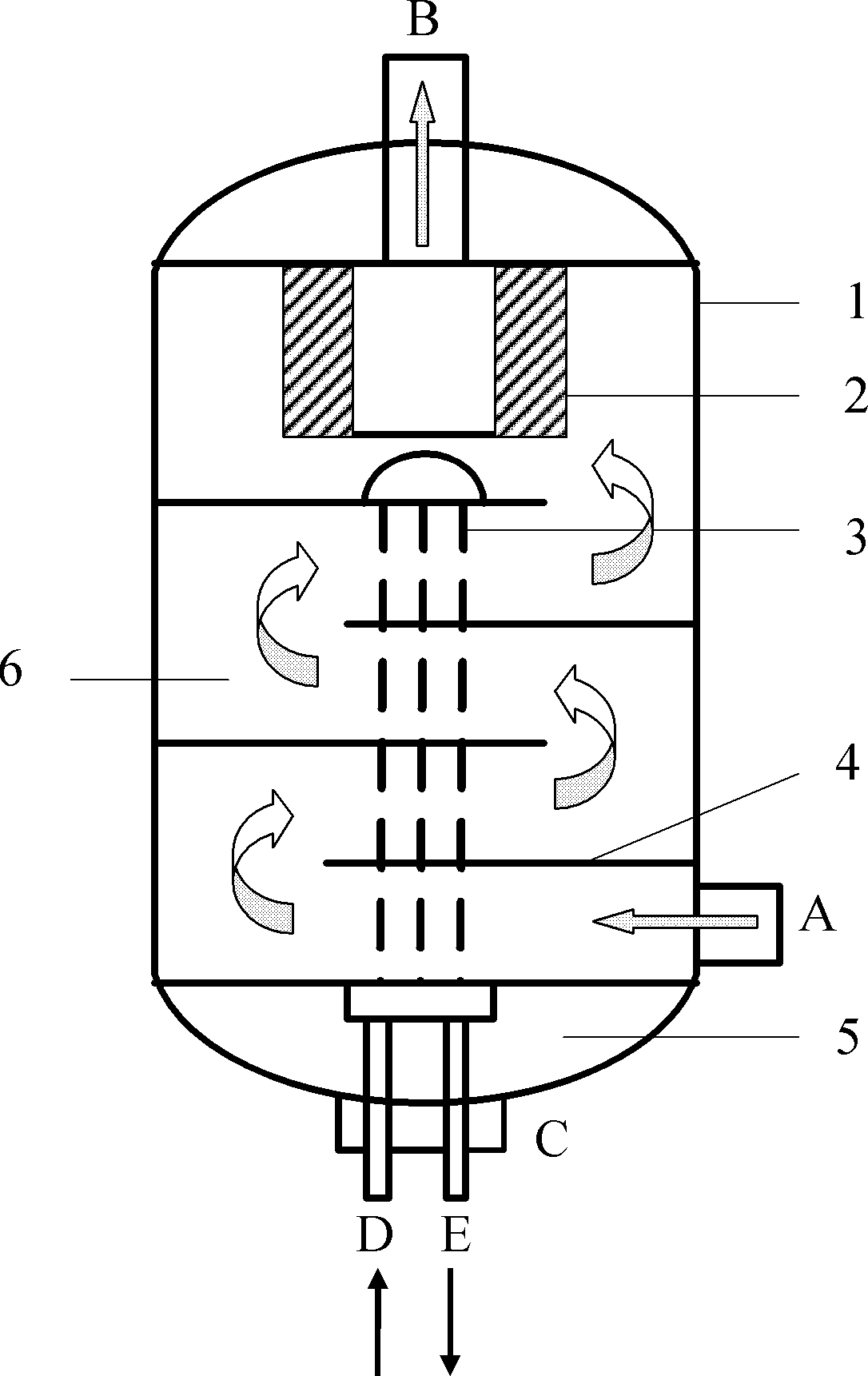
[0021] The upper and lower ends of the cylindrical separator housing 1 (with a diameter of 40 centimeters and a height of 1 meter) placed vertically in the axial direction of this embodiment are respectively equipped with a top cover and a bottom oil collection chamber 5; at the center of the lower end of the top cover A hollow annular adsorption filter 2 is installed, and the inner shell wall of the cylindrical separator housing 1 below the hollow annular adsorption filter 2 is equipped with 4 horizontal baffles 4 to prevent staggering, and the outer edges of the horizontal baffles 4 exceed all The radial center of the cylindrical separator housing 1; the cooling coil 3 penetrates through the lower end of the cylindrical separator housing 1 (or the bottom oil collection chamber 5), and then passes through the baffles from bottom to top in turn 4. After passing through the uppermost baffle plate, bend and pass through each baffle plate 4 from top to bottom in turn, and finally ...

Embodiment 2

[0025] The upper end face and the lower end face of the cylindrical separator housing 1 (diameter is 60 centimeters, height is 1.5 meters) of the axially vertical placement of present embodiment are respectively equipped with top cover and bottom oil collection cavity 5; Hollow top cover The lower end is equipped with a hollow annular adsorption filter 2, and 20 horizontal baffles 4 are installed on the inner shell wall of the cylindrical separator housing 1 below the hollow annular adsorption filter 2, and the outer edge of the horizontal baffle 4 exceeds the circle. The radial center of the cylindrical separator housing 1; the cooling coil 3 penetrates through the lower end of the cylindrical separator housing 1 (or the bottom oil collection chamber 5), and then passes through the baffles 4 from bottom to top in turn, After passing through the uppermost baffle plate, it is bent and passes through each baffle plate 4 from top to bottom in turn, and finally protrudes from the l...

Embodiment 3

[0027] This embodiment is basically the same, the difference is that there is one horizontal baffle.


PUM


Abstract

The invention provides a condensing gathering separator for separating lubricating oil from refrigerant. The condensing gathering separator comprises a cylindrical separator shell, a top cover, a bottom oil-gathering chamber, a hollow annular adsorbing filter, at least one horizontal baffle, a cooling coil, a mixer air inlet, a refrigerant outlet and a lubricating oil outlet, wherein the cylindrical separator shell is vertically placed along axial direction; the top cover and the bottom oil-gathering chamber are respectively mounted at the upper and lower ends of the shell; the hollow annular adsorbing filter is mounted at the lower end of the hollow top cover; the horizontal baffle is mounted under the adsorbing filter on an inner wall of the shell; an outer edge of the horizontal baffle exceeds the radial center of the shell; the cooling coil passes through each baffle in turn; two ends of the cooling coil respectively extend out of the shell; a cooling medium inlet is arranged at one end while a refrigerating medium outlet is arranged at the other end; the mixer air inlet is arranged on one side of the lower part of the shell; the refrigerant outlet is arranged at the top of the shell; and the lubricating oil outlet is arranged at the lower end of the bottom oil-gathering chamber. The condensing gathering separator is simple and compact in structure; various separating effects, such as impacting, condensing gathering, gravity settling, adsorbing filtering, and the like, are integrated in one separator; the refrigerant and the lubricating oil are thoroughly separated; and the higher demand on separating the lubricating oil from the refrigerant is met.

Description

technical field [0001] The invention belongs to the field of separators, in particular to a condensation trap separator for separating lubricating oil from refrigerant. Background technique [0002] The liquefaction process technology using multiple mixed refrigerants has been successfully applied in the field of liquefied natural gas for many years, and has become the leading liquefaction technology in the field of liquefied natural gas, accounting for more than 90% of the large-scale liquefaction plants in this field. The low-pressure mixed refrigerant liquefaction process technology is similar to it in terms of refrigeration principle. The core refrigeration effect is still the throttling effect of the actual gas. The difference is that its core is based on the self-recuperation of the mixed refrigerant to achieve low-temperature refrigeration. (such as ZL200910090844.9). Compared with the high-pressure refrigeration process used in the traditional LNG process, the low-p...

Claims


Application Information

Patent Timeline
Patent Type & Authority Applications(China)
IPC IPC(8): F25B43/02
Inventor 公茂琼董学强吴剑峰胡勤国
Owner TECHNICAL INST OF PHYSICS & CHEMISTRY - CHINESE ACAD OF SCI
Why Eureka
Try Eureka