Cold atom beam interference gyro device

A cold atomic beam and atomic beam technology, applied in the field of inertial measurement, can solve the problem of low signal extraction accuracy

Active Publication Date: 2014-08-06
TSINGHUA UNIV
View PDF2 Cites 0 Cited by
  • Summary
  • Abstract
  • Description
  • Claims
  • Application Information

AI Technical Summary

Problems solved by technology

[0015] The purpose of the present invention is to: overcome the deficiencies of current existing pulsed cold atom sources and hot atomic beams in the application of atomic interferometers; overcome the shortcomings of high requirements for environmental stability and low signal extraction accuracy of atomic interferometers, and Provide a cold atomic beam interference gyro device, which has the advantages of obtaining high-precision gyro absolute rotation signals with good optical characteristics, large flux, consistent energy state, compact structure, stable performance, low environmental requirements, and the ability to extract relative inertial space , rotation signal sampling speed is high, linearity is good, dynamic range is large

Method used


Image

  • Cold atom beam interference gyro device
  • Cold atom beam interference gyro device
  • Cold atom beam interference gyro device

Examples


Embodiment 1

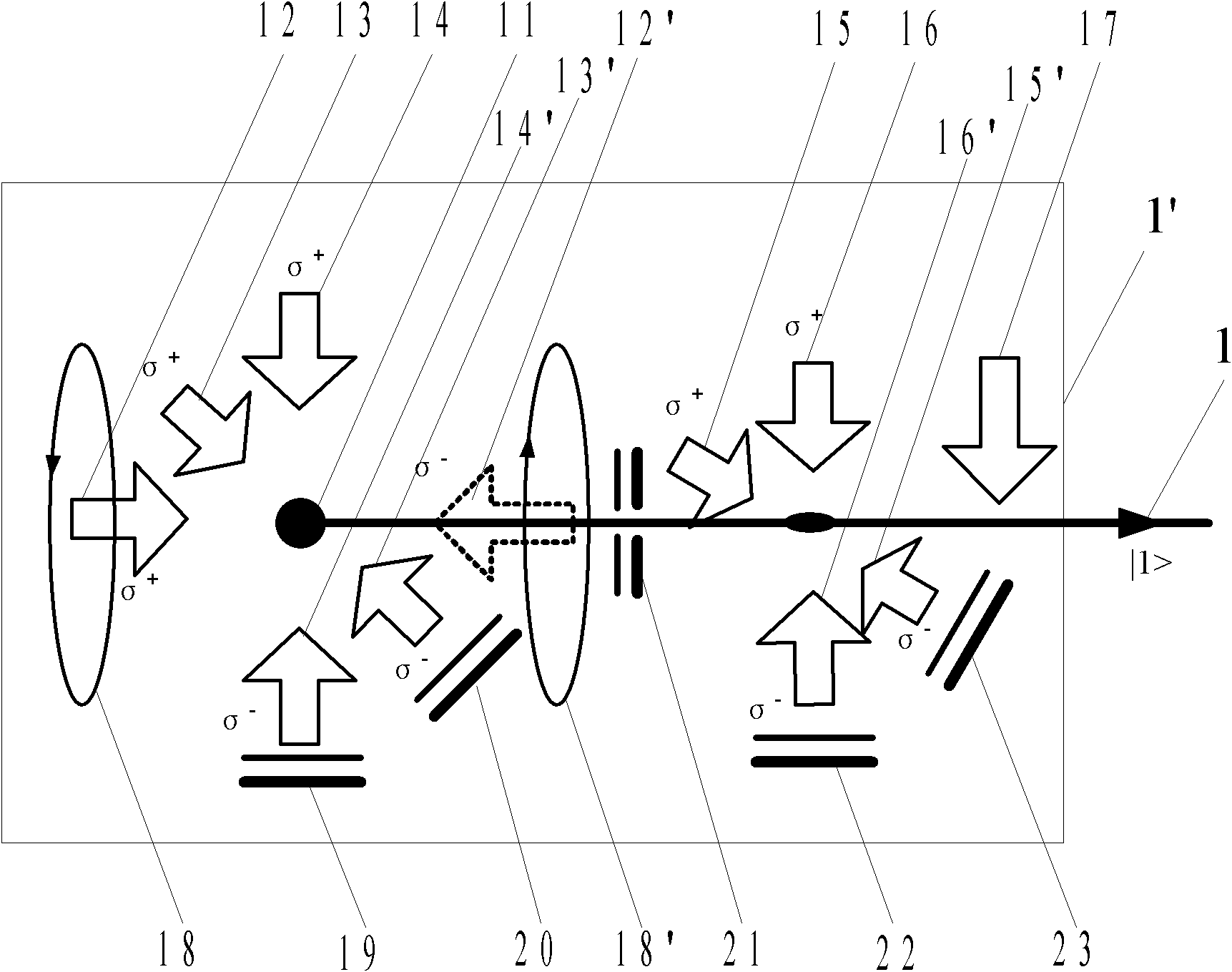
[0089] Attached below figure 2 , 3 and Examples to further describe the device and method for generating cold atomic beams of the present invention.

[0090] The atomic vapor in the vacuum chamber is cooled by an asymmetric three-dimensional magneto-optical trap (3D-MOT) and trapped to form a cold atom cloud 11, and a quarter of the hole with a small hole is installed vertically in the direction of the incident cooling laser beam 12 A wave plate / mirror group 21; the existence of the small hole unbalances the radiation pressure of the laser on the atoms in this direction, so that the trapped atomic cloud is pushed out from the small hole to form a cold atomic beam. After the cold atomic beam emerges from the small hole, use the two-dimensional optical glue technology to compress and collimate the outgoing cold atomic beam, and finally use the state preparation laser beam 17 to prepare the cold atomic beam to the |1> state of the atomic energy level A cold atomic beam 1 in an a...

Embodiment 2

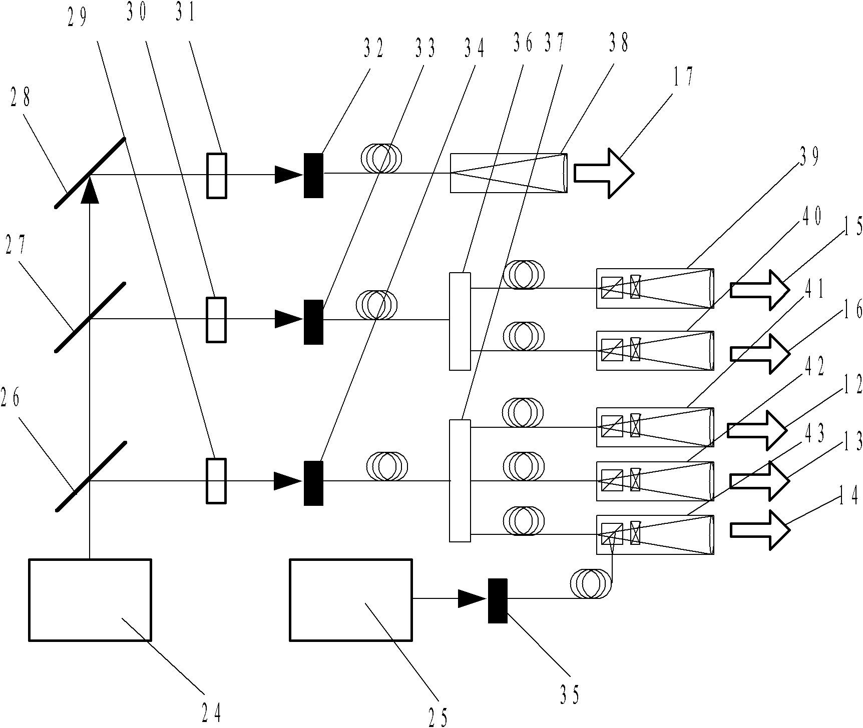
[0105] Combine below figure 1 , 2 , 4 and Examples further describe in detail the optical grating device based on the two-photon stimulated Raman transition principle of the present invention.

[0106] The first grating 2 , the second grating 3 and the third grating 4 can be mechanical gratings or optical gratings formed by using a laser standing wave field. The present invention adopts an optical grating based on the principle of two-photon stimulated Raman transition of a continuous through-beam Raman beam, which is prepared as follows:

[0107] The output light of the third laser 44 is divided into two parts through an optical beam splitter 49, and a part of the laser is modulated by an electro-optical modulation 45 to obtain seed light with three modes of both sidebands and carrier frequency; the seed light is injected into a semiconductor laser diode 46 Inside, perform frequency-selective injection-locked amplification; the output light passes through the 1 / 2 wave plate...

Embodiment 3

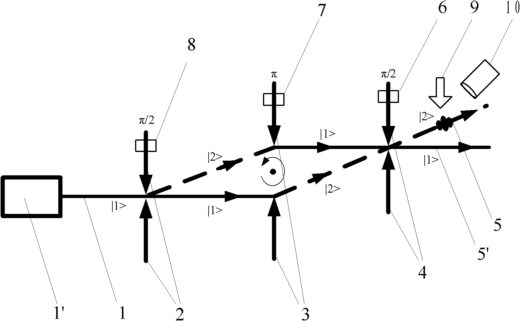
[0110] Attached below Figure 4 , 5 , 6 and specific embodiments will further describe in detail the extraction of the gyroscope rotation signal of the present invention.

[0111] Here we take the π / 2-π-π / 2 configuration stimulated Raman transition atomic interference as an example:

[0112] 1) Build a cold atomic beam interference system, that is, the cold atomic beam 1 is under the action of the first grating 2 (π / 2 phase Raman optical grating), the stimulated Raman transition realizes atomic beam splitting, and the second grating 3 (π phase Raman optical grating) realizes the reflection of the atomic beam through the stimulated Raman transition, and the third grating 4 (π / 2 phase Raman optical grating) realizes the sum beam of the atomic beam through the stimulated Raman transition, and obtains |2> state atomic interference signal 5;

[0113] 2) Through the first phase modulator 8, the second phase modulator 7 and the third phase modulator 6 (using the differential acous...


PUM


Abstract

The invention discloses a cold atom beam interference gyro device, which comprises a cold atom beam system, a coherent atom beam operating system, and a gyro rotating signal extracting system. The cold atom beam system continuously emits | 1 > state cold atom beams as a matter wave source; the coherent atom beam operating system is composed of three gratings placed on the emitting path of | 1 > state cold atom beams in turn, and three phase modulators for modulating the phases of three gratings, respectively; | 1 > state cold atom beams orderly enter the three grating for splitting, reflecting and splitting again so as to obtain | 2 > energy state atom beam and | 1 > state cold atom beam interference signals; the | 2 > energy state atom beam interference signals are induced to produce fluorescent signals by the probing laser of the gyro rotating signal extracting system, a photoelectric detecting device detects the fluorescent signals and transmits the signals to a computer for processing to obtain gyro rotating angular-speed signals. With this device disclosed by the invention, high-precision gyro absolute rotating signals relative to inertial space and with high requirement on environment can be obtained.

Description

technical field [0001] The invention belongs to an interference gyro device in the field of inertial measurement, in particular to a cold atomic beam interference gyro device. Background technique [0002] At present, there are two main types of Mach-Zehnder atomic interferometers with three optical gratings: [0003] 1) Spatial atom interferometer of thermal atomic beam, as described in Document 1: T.L.Gustavson, P.Bouyer, M.A.Kasevich, Phys.Rev.Lett., 1997, 78:2046-2049. [0004] 2) Temporal atomic interferometer for pulsed cold atomic clouds, such as P.Cheinet, B.Canuel, F.Pereira Dos Santos, A.Gauguet, F.Leduc, A.Landragin, IEEE Trans.Instrum.Meas, 2008 , 57:1141-1148 recorded. [0005] For the first type of thermal atomic beam atomic interferometer, the longitudinal velocity of the atomic beam used is relatively high (the longitudinal velocity is the moving speed of the atomic beam in the forward direction, usually >200m / s), but for the atomic interferometer to hav...

Claims


Application Information

Patent Timeline
Patent Type & Authority Patents(China)
IPC IPC(8): G01C19/58G01C19/64
Inventor 冯焱颖薛洪波周兆英王晓佳朱常兴叶雄英
Owner TSINGHUA UNIV
Why Eureka
Try Eureka