Video Aquatic Sampling Methods

A technology of aquatic organisms, video, applied in the direction of sampling devices, etc.

Inactive Publication Date: 2017-02-22
HARBIN DONGZHUAN TECH
View PDF4 Cites 0 Cited by
  • Summary
  • Abstract
  • Description
  • Claims
  • Application Information

AI Technical Summary

Problems solved by technology

Existing water sample samplers have no sampling function for fixed deep waters and the use of video camera technology and computer technology for purposeful and accurate collection of

Method used


Image

  • Video Aquatic Sampling Methods
  • Video Aquatic Sampling Methods

Examples


Embodiment 1

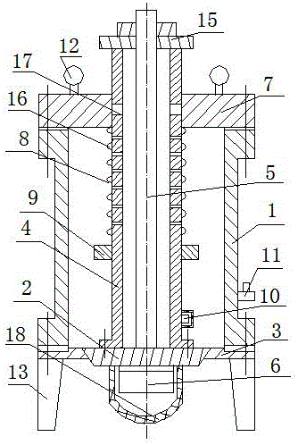
[0023] A video aquatic life sampler, which consists of: a housing 1 with a stakeout valve 11, the lower end of the housing is connected to a lower end cover 3 with a lower cone movable door 2, and the upper end of the lower cone movable door is connected to The ventilation cavity 4 in the connecting rod of the lower movable door of the sampler is equipped with a cable 5 in the ventilation cavity of the connecting rod of the lower movable door of the sampler, and the lower end of the movable door of the lower cone is connected to the video through the cable. Rotatable angle camera 6, the ventilation cavity in the connecting rod of the lower movable door of the sampler and the cable pass through the upper end cover 7, and the ventilation cavity in the connecting rod of the lower movable door of the sampler is covered with a compression spring 8. The compression spring is supported by the lower support ring 9, and the water temperature sensing probe 10 is connected outside the ven...

Embodiment 2

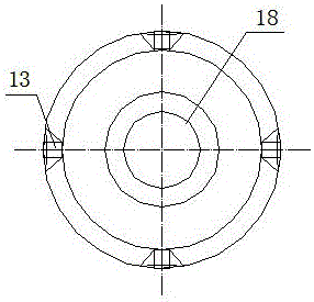
[0025] In the video aquatic life sampler described in Embodiment 1, the upper end of the upper end cover is connected to the traction rope suspension ring 12, the lower end of the lower end cover is connected to the bracket 13, and the signal line of the water temperature sensing probe is connected to the cable. The upper end of the ventilation cavity in the connecting rod of the lower movable door has a cable lock nut 15 passing through the cable, and the cone part of the lower cone movable door and the upper cone part of the lower end cover cooperate with each other to form an aquatic organism. The sampling door of the sampler, the ventilation cavity in the connecting rod of the lower movable door of the sampler is located between the upper end cover and the support ring, and there is an exhaust hole 16 in the cavity, and the lower movable door of the sampler is The ventilation cavity in the door linkage is located at the matching middle position of the upper end cover and ha...

Embodiment 3

[0027] In the video aquatic biological sampler described in embodiment 1 or 2, the housing and the camera protective cover are made of plexiglass material, the upper end cover, the lower end cover, and the protective bracket , The ventilation cavity inside the connecting rod of the movable door under the sampler is made of stainless steel.


PUM


Abstract

Provided are a video sampler for aquatic organism and a sampling method. Recently, along with the rapid development of industries along rivers and lasting of global greenhouse effect, pollution to the river and lakes is on the rise. The video sampler for the aquatic organism comprises a casing (1) provided with a lofting valve (11). The lower end of the casing is connected with a lower end cover (3) provided with a lower cone movable door (2), the upper end of the lower cone movable door is connected with a sampler lower movable door connection door inner ventilating cavity (4), a cable line (5) is installed in the sampler lower movable door connection door inner ventilating cavity, and the lower end of the lower cone movable door is connected with a video angle-rotatable camera (6) through a cable line, the sampler lower movable door connection door inner ventilating cavity and the cable line penetrate through an upper cover (7), a compression spring (8) is sleeved outside the sampler lower movable door connection door inner ventilating cavity and is supported by a lower support ring (9), and a water temperature sensing probe (10) is connected to the outside of the sampler lower movable door connection door inner ventilating cavity. The video sampler for the aquatic organism and the sampling method are used for sampling the aquatic organism.

Description

[0001] Technical field: [0002] The invention relates to a video aquatic organism sampler and a sampling method. [0003] Background technique: [0004] In recent years, with the rapid development of industries along the river and the continuation of the global greenhouse effect, the pollution of rivers, rivers and lakes has become increasingly serious. Directly affect the sound development of animal husbandry and agriculture, especially serious pollution to the quality of people's daily drinking water; directly change the sustainable virtuous cycle of the biological chain of aquatic organisms in rivers, rivers, and lakes, causing many aquatic organisms to be on the verge of extinction the edge of. For example, oily sewage from oil refineries, residual chemical waste from chemical plants, and other nuclear material leaks caused by the Japanese tsunami are threatening aquatic organisms in adjacent sea waters, which have received great attention from the state. Tracking and ce...

Claims


Application Information

Patent Timeline
IPC IPC(8): G01N1/02G01N1/10
Inventor 王海涛刘矢蒋博轩蒋树义
Owner HARBIN DONGZHUAN TECH
Why Eureka
Try Eureka