Method for identifying internal and external faults of bus area through simulation after test
A technology of post-test simulation and busbar area, applied in the direction of fault location, etc., can solve the problems of refusal to operate, protection of misoperation, etc.
- Summary
- Abstract
- Description
- Claims
- Application Information
AI Technical Summary
Problems solved by technology
Method used
Image
Examples
Embodiment 1
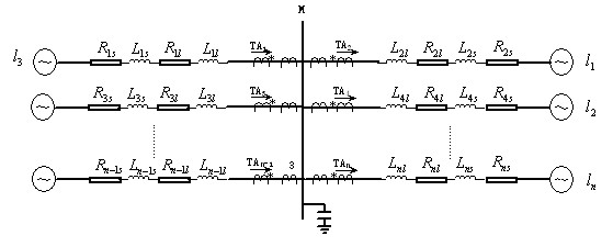
[0061] Example 1: The system is single-bus connection, three-circuit outgoing line, and the line is a split conductor. A distributed parameter model considering the influence of frequency variation (J.Marti line model according to frequency) is adopted, and the length of the outgoing line is 300km. Among them, , , , , , , A phase ground fault occurs in the system, and the grounding resistance is 10 ohms.
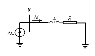
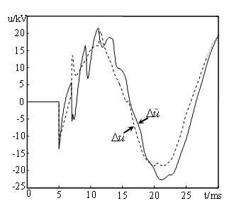
[0062] When an internal fault occurs in the bus, the power network is equivalent to a Circuit model, in a short time window, at the measured bus Modulus fault component voltage and component current , and then analyze Model the fault component network properties, using Kirchhoff's voltage theorem (The current direction is positive when flowing into the busbar), and the voltage at the busbar is simulated and calculated , and then calculate the analog voltage Waveform and measured voltage Correlation coefficient of waveform , will simulate the volt...
Embodiment 2
[0069] Embodiment 2: The structure and parameters of the system bus are the same as those in Embodiment 1. A phase-to-ground fault (A-G) occurs on outgoing line 1, the fault location is 200km away from the busbar, and the transition resistance is 10 ohms. The length of the short data window (time window) is 3ms, and the sampling frequency is 20kHz.
[0070] The sampling frequency is 20kHz, the short time window is 3ms, and the data length is measured N =60. After the failure of outgoing line 1, according to the same method as in embodiment 1, according to the measured Modulus fault component current and system positive sequence resistance value , Positive sequence inductance value , calculate the analog voltage at the busbar and the correlation coefficient between the analog voltage waveform and the measured voltage waveform, and get =-0.5815<0, according to which it is judged as non-bus fault;
Embodiment 3
[0071] Embodiment 3: The structure and parameters of the system bus are the same as in Example 1. A phase-to-ground fault (A-G) occurs on outgoing line 2, the fault location is 150km away from the busbar, and the transition resistance is 10 ohms. The length of the short data window (time window) is 3ms, and the sampling frequency is 20kHz.
[0072] The sampling frequency is 20kHz, the short time window is 3ms, and the data length is measured N=60. After the failure of outgoing line 2, according to the same method as in embodiment 1, according to the measured Modulus fault component current and system positive sequence resistance value , Positive sequence inductance value , calculate the analog voltage at the busbar and the correlation coefficient between the analog voltage waveform and the measured voltage waveform, and get =-0.6348<0, according to which it is judged as non-bus fault;
PUM
 Abstract
Description
Claims
Application Information
 - R&D
- Intellectual Property
- Life Sciences
- Materials
- Tech Scout
- Unparalleled Data Quality
- Higher Quality Content
- 60% Fewer Hallucinations
Browse by: Latest US Patents, China's latest patents, Technical Efficacy Thesaurus, Application Domain, Technology Topic, Popular Technical Reports.
© 2025 PatSnap. All rights reserved.Legal|Privacy policy|Modern Slavery Act Transparency Statement|Sitemap|About US| Contact US: help@patsnap.com


