Plugging photoelectric composite connector

A technology for optoelectronic composite and optoelectronic composite cables, which is applied in the direction of connection, coupling of optical waveguides, and two-component connection devices, etc., can solve the problems of difficult construction, maintenance and replacement, many joints, and increased cost of connector sealing and connection.

Active Publication Date: 2012-07-04
8TH RES INST OF CETC
View PDF5 Cites 13 Cited by
  • Summary
  • Abstract
  • Description
  • Claims
  • Application Information

AI Technical Summary

Problems solved by technology

However, this way that the optical cable and the cable need to be sealed and connected separately leads to too many joints and more parts exposed to wat

Method used


Image

  • Plugging photoelectric composite connector
  • Plugging photoelectric composite connector
  • Plugging photoelectric composite connector

Examples


Embodiment Construction

[0022] The specific embodiment of the present invention is described in detail below in conjunction with accompanying drawing:

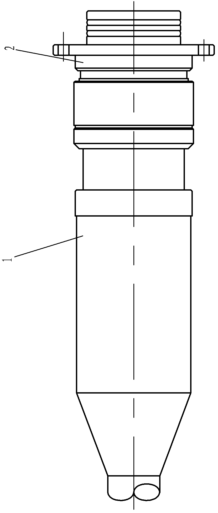
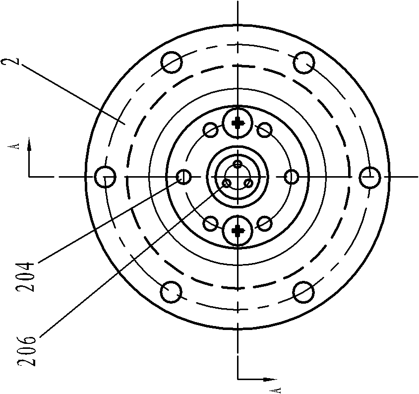
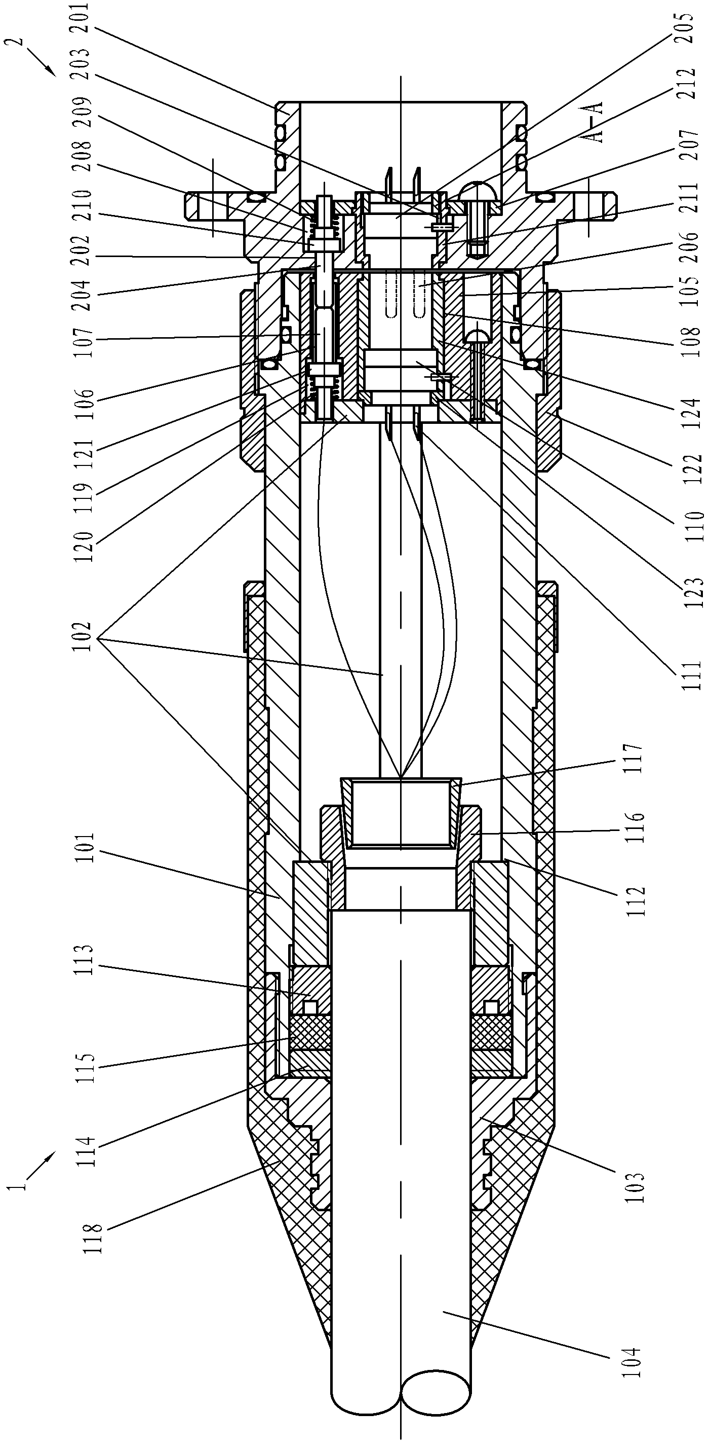
[0023] refer to Figure 1 to Figure 3 As shown, the pluggable photoelectric composite connector of this embodiment includes a plug 1 and a socket 2 that is tightly connected to the thread, and the left side of the plug 1 is provided with an integrally formed vulcanized sealing layer 118, wherein:

[0024] Plug 1 comprises shell 101, and support 102 is installed in the shell 101 (as Figure 7 to Figure 9 As shown), the left end of the bracket 102 is equipped with a reserved photoelectric composite cable 104, and the left end of the casing 101 is threadedly connected with a tail sleeve 103, and the left end of the reserved photoelectric composite cable 104 protrudes from the left end of the tail sleeve 102, and is connected to the tail sleeve 102. The joint of the left end of the sleeve 102 is sealed, and the left side of the tube shell 101 is also pr...


PUM


Abstract

The invention discloses a plugging photoelectric composite connector which comprises a plug and a socket; a pre-reserved photoelectric composite cable which is protruded outside is arranged in the left end of the plug; a plug center hole and a plurality of first openings are arranged in the right end of the plug; an optical inner insert core is arranged in the first opening; a first electric insert core is arranged in the plug center hole; a plurality of electrically connected jacks are arranged in the first electric insert core; a contact is arranged in each electrically connected jack; the optical fiber inner insert core and the contact are connected and coupled with the right end of the pre-reserved photoelectric composite cable; a socket center hole and a plurality of second openings are arranged on the left end of the socket; optical fiber outer insert cores are arranged in the second openings; the left end of each optical fiber outer insert core is inserted leftwards into the first opening which corresponds to the optical fiber outer insert core and is contacted with the optical fiber inner insert core in the first opening; a second electric insert core is arranged in the socket center hole; a plurality of contact pins are arranged on the second electric insert core; and the left end of each contact pin is inserted leftwards into the electrically connected jack which corresponds to the contact pin and is contacted with the contact in the electrically connected jack.

Description

technical field [0001] The invention relates to an underwater optical fiber networking device, in particular to a pluggable photoelectric composite connector. Background technique [0002] The watertight connector is used in the wired base array in the underwater tracking and measurement system. And other series of data are transmitted to the control room, and at the same time, the control signals and power in the shore base are transmitted to the underwater front-end array to provide power for various modules inside the array. It is the comprehensive operating parameters and technical indicators of the underwater working platform. reflect. [0003] my country has a vast ocean, and ocean detection has become an important link in the country's development. At the same time, the coastal defense construction of my country's coastline countries is also in a period of great development. All underwater detection and underwater weapon trajectory are connected by watertight connect...

Claims


Application Information

Patent Timeline
IPC IPC(8): G02B6/38H01R13/523H01R24/00
Inventor 叶杨高朱家远
Owner 8TH RES INST OF CETC
Why Eureka
Try Eureka