Display substrate and manufacturing method thereof

A production method and display technology, applied in the direction of instruments, nonlinear optics, optics, etc., can solve the problems of inaccurate alignment, lower yield rate of liquid crystal panels, etc., and achieve the effect of solving heavy industry

Inactive Publication Date:
View PDF5 Cites 8 Cited by
  • Summary
  • Abstract
  • Description
  • Claims
  • Application Information

AI Technical Summary

Problems solved by technology

[0004] In addition, since the polarizer needs to be fixed on the color filter or thin film transistor substrate through adhesive, it needs to go through a step of pasting the polarizer, and it may be damaged due to inaccurate alignment during pasting. Decrease the yield rate of LCD panel

Method used


Image

  • Display substrate and manufacturing method thereof
  • Display substrate and manufacturing method thereof
  • Display substrate and manufacturing method thereof

Examples


Embodiment Construction

[0041] The following will clearly illustrate the spirit of the present invention with drawings and detailed descriptions. Anyone with ordinary knowledge in the relevant technical field can change and modify the technology taught by the present invention after understanding the preferred embodiments of the present invention. It does not depart from the spirit and scope of the present invention.

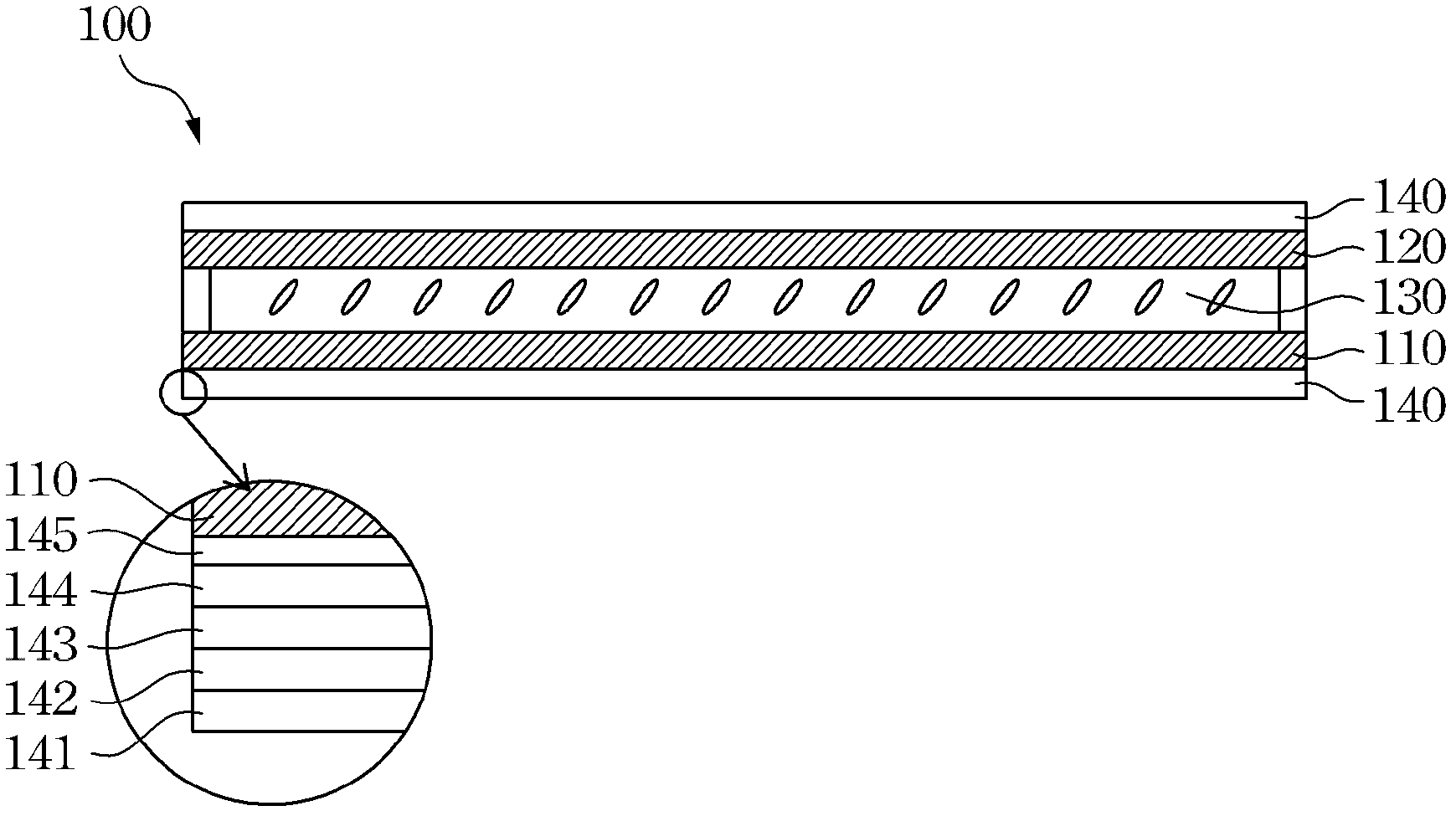
[0042] Reference figure 1 , Which shows a cross-sectional view of a conventional LCD panel. The conventional liquid crystal panel 100 includes a thin film transistor substrate 110, a color filter 120, a liquid crystal layer 130 sandwiched between the color filter 120 and the thin film transistor substrate 110, and are attached to the thin film transistor substrate 110 and the color filter respectively. Two polarizers 140 on the light sheet 120. The polarizer 140 includes a surface protective film 141, a first protective layer 142, a polarizing base 143, a second protective layer 144, and...


PUM


Abstract

The invention provides a display substrate having both the color filtering and the polarizing functions or having both the driving and the polarizing functions so as to reduce the thickness of a liquid crystal panel. The invention also provides a method for manufacturing the display substrate.

Description

【Technical Field】 [0001] The present invention relates to a liquid crystal display, and in particular to a display substrate used for a liquid crystal display and a manufacturing method thereof. 【Background technique】 [0002] Liquid Crystal Display (LCD) has the advantages of high image quality, small size, light weight, low voltage drive, low power consumption and wide application range, so it has been widely used in portable TVs, mobile phones, video cameras Consumer electronics or computer products such as video players, notebook computers, and desktop displays have become the mainstream displays. [0003] The traditional liquid crystal display structure mainly includes an outer frame, a liquid crystal panel, and a backlight module. The liquid crystal panel includes a lower polarizer, a thin film transistor substrate, a liquid crystal layer, a color filter, and an upper polarizer. Since the development trend of modern products is light and thin, traditional liquid crystal pane...

Claims


Application Information

Patent Timeline
Patent Type & Authority Applications(China)
IPC IPC(8): G02F1/1335G02F1/1333
Inventor 陈家承洪铭钦张钧杰
Why Eureka
Try Eureka