
Automatic focusing method and image capturing system

An auto-focus and image capture technology, applied in the auto-focus field of the image capture system, can solve problems such as falling or different placement, poor focus, and changes in refractive index

Inactive Publication Date: 2012-07-04
ABILITY ENTERPRISE CO LTD
View PDF5 Cites 6 Cited by
  • Summary
  • Abstract
  • Description
  • Claims
  • Application Information

AI Technical Summary

Problems solved by technology

[0003] However, digital cameras are often affected by external environmental changes, such as temperature or humidity changes, or by external forces, such as falling or different placements, causing the focus lens to shift, making the real infinity focus position different from the calibration value before leaving the factory , causing the focus lens to fail to move to the correct focus position, allowing users to shoot blurry images due to poor focus or failure
Especially for lenses made of plastic, since the plastic material itself is easy to absorb moisture, it is easy to cause changes in the refractive index of the lens
In addition, the lens may expand and contract with the external temperature and humidity, or the moisture content may change, resulting in a change in the refractive index
[0004] It can be seen that the above-mentioned existing imaging technology obviously still has inconvenience and defects in method and use, and needs to be further improved urgently.
In order to solve the above-mentioned existing problems, relevant manufacturers have tried their best to find a solution, but no suitable design has been developed for a long time, and there are no suitable methods and methods to solve the above-mentioned problems. This is obviously a problem that relevant industry players are eager to solve

Method used


Image

  • Automatic focusing method and image capturing system
  • Automatic focusing method and image capturing system
  • Automatic focusing method and image capturing system

Examples


Embodiment Construction

[0037] In order to further explain the technical means and effects that the present invention adopts to achieve the intended purpose of the invention, below in conjunction with the accompanying drawings and preferred embodiments, the specific implementation methods, methods, Steps, features and effects thereof are described in detail below.

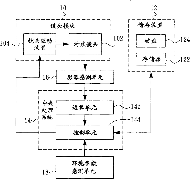
[0038] figure 1A functional block diagram of an image capturing system according to an embodiment of the present invention is shown. The image capture system of this embodiment is mainly used to perform autofocus. The image capture system can be a camera, video camera, mobile phone, personal digital assistant (Personal Digital Assistant, PDA), digital music (MPEG Audio Layer 3, MP3 ) player or webcam, but not limited thereto. In this embodiment, the image capture system mainly includes a lens module 10 , a storage device 12 and a central processing system 14 . In addition, the image capture system may further include an image sensing u...


PUM


Abstract

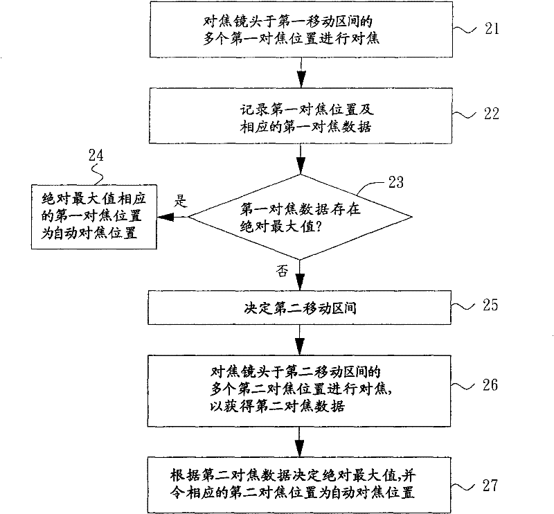
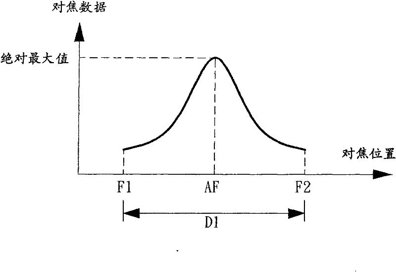
The invention relates to an automatic focusing method and an image capturing system. The automatic focusing method comprises the following steps of: focusing in a first movement interval of a focusing mode by using a focusing lens, and recording a plurality of first focusing positions and a plurality of corresponding first focusing data; then judging whether an absolute maximum value exists in the first focusing data; if not, determining a second movement interval, and enabling the focusing lens to focus in the second movement interval to obtain a plurality of second focusing data; and determining the absolute maximum value according to the second focusing data, and enabling a second focusing position corresponding to the absolute maximum value to be an automatic focusing position.

Description

technical field [0001] The invention relates to an imaging technology, in particular to an automatic focusing method of an image capture system. Background technique [0002] Before the digital camera leaves the factory, it usually calibrates the infinity focus position of the focus lens, and records the corrected infinity focus position in the internal memory of the digital camera. When the user half-presses the shutter button to start the auto-focus procedure, the digital camera uses the stored infinity focus position as a reference to move the focus lens to focus. [0003] However, digital cameras are often affected by external environmental changes, such as temperature or humidity changes, or by external forces, such as falling or different placements, causing the focus lens to shift, making the real infinity focus position different from the calibration value before leaving the factory , causing the focus lens to fail to move to the correct focus position, allowing use...

Claims


Application Information

Patent Timeline
IPC IPC(8): G03B13/36G02B7/36H04N5/232
Inventor 许盛雄
Owner ABILITY ENTERPRISE CO LTD
Learn More