Rotor structure for fault-tolerant permanent magnet electromotive machine

A rotor structure and permanent magnet technology, applied in the direction of magnetic circuit shape/style/structure, electric components, magnetic circuit rotating parts, etc., can solve the problems of sacrificing power efficiency and increasing incremental cost

Active Publication Date: 2012-07-04
GENERAL ELECTRIC CO
View PDF6 Cites 4 Cited by
  • Summary
  • Abstract
  • Description
  • Claims
  • Application Information

AI Technical Summary

Problems solved by technology

Therefore, such measures may sacrifice power efficiency and increase incremental cost

Method used


Image

  • Rotor structure for fault-tolerant permanent magnet electromotive machine
  • Rotor structure for fault-tolerant permanent magnet electromotive machine
  • Rotor structure for fault-tolerant permanent magnet electromotive machine

Examples


Embodiment Construction

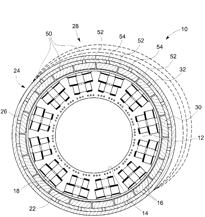
[0041] As discussed in more detail below, aspects of the invention relate to fault-tolerant permanent magnet machines that may include fractional slot pitch concentrated windings. As used herein, the term "fault tolerance" refers to magnetic and physical separation between the various machine coils / phases while reducing noise, torque ripple and harmonic flux components.

[0042] The inventors of the present invention have proposed an innovative and state-of-the-art method suitable for substantially reducing electromagnetic rotor losses generally associated with the frequency spectrum of the spatial harmonics of fractional-slot-pitch concentrated windings. As mentioned before, this spectrum includes many asynchronous harmonics that do not add useful MMF. The proposed method can be advantageously configured to maximize the reluctance encountered by asynchronous harmonics, while having little effect on the useful or synchronous MMF components, thereby maximizing the power density...


PUM


Abstract

A rotor structure (24) for a fault-tolerant permanent magnet electromotive machine (10) is provided. A back-core lamination (28) is disposed around a plurality of permanent magnets (30). The back-core lamination (28) comprises a plurality of high-reluctance regions (50) arranged to attenuate asynchronous magnetic flux components while avoiding synchronous magnetic flux components. The asynchronous and synchronous magnetic flux components result from spatial harmonic components of a plurality of fractional-slot concentrated windings (18) of a stator (12) of the machine.

Description

technical field [0001] The present invention relates generally to permanent magnet (PM) motors, such as generators and / or electric motors, and more particularly to fault-tolerant PM machines. Background technique [0002] Electric motors are known to generate high magnitude magnetic fields using permanent magnets (PM) as the primary mechanism due to inductive induction. Unlike machines that include electromagnets that can be electrically controlled (eg, selectively switched on or off), the PM remains on. That is, the magnetic field generated by the PM is persistent due to the inherent ferromagnetic properties of the PM. Therefore, if a motor with PM experiences a failure, it may not be convenient to stop the machine because of the persistent nature of the PM's magnetic field causing the machine to continue running. Such faults may be in the form of fault currents due to defects in the stator windings or mechanical faults caused by defective or worn mechanical components pr...

Claims


Application Information

Patent Timeline
Patent Type & Authority Applications(China)
IPC IPC(8): H02K1/27H02K1/28
CPCH02K1/2786H02K2213/12H02K29/03H02K1/2791
Inventor M·沙A·M·F·艾尔-雷菲
Owner GENERAL ELECTRIC CO
Why Eureka
Try Eureka