Radial rotor structure for permanent magnet synchronous motor

A rotor structure and rotor technology, applied in the direction of magnetic circuit shape/style/structure, magnetic circuit rotating parts, etc., can solve the problems of unsuitable motors, occupying the effective length of the rotor, breaking positioning and tension bolts, etc., and achieving long service life , to avoid magnetic flux leakage phenomenon, not easy to break the effect

Active Publication Date: 2014-06-11
ZHEJIANG UNIV
View PDF5 Cites 0 Cited by
  • Summary
  • Abstract
  • Description
  • Claims
  • Application Information

AI Technical Summary

Problems solved by technology

[0008] This kind of permanent magnet motor rotor has the following disadvantages: 1. The centrifugal force on the rotor pole piece is jointly borne by the end plate, the partition plate and the positioning tension bolts, that is to say, the positioning tension bolts that fix the rotor unit need to bear the bending moment. When the rotor When rotating at high speed, the centrifugal force is very large, which may easily cause the positioning and tension bolts to be broken by centrifugal force, that is to say, the rotor is not suitable for high-speed rotating motors.
2. Although there is a magnetic isolation groove in the iron core, there are still connecting parts between the adjacent permanent magnets, and the magnetic fields of the permanent magnets of adjacent two poles are easily connected directly through the connecting parts of the iron cores between the permanent magnets, resulting in magnetic flux leakage , that is to say, the structure cannot avoid magnetic flux leakage and the amount of magnetic flux leakage is serious
3. The partition is set between two adjacent rotor units, and the thickness of the partition occupies the effective length of the rotor along the axial direction; when the number of rotor units used in the rotor is large and the rotor partition is thick, the rotor The effective length will be drastically reduced, affecting the electromagnetic performance of the rotor

Method used


Image

  • Radial rotor structure for permanent magnet synchronous motor
  • Radial rotor structure for permanent magnet synchronous motor
  • Radial rotor structure for permanent magnet synchronous motor

Examples


Embodiment Construction

[0027] With reference to accompanying drawing, further illustrate the present invention:

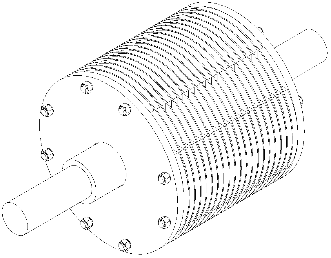
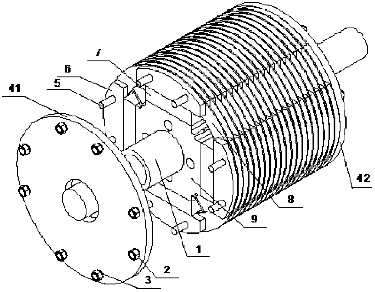
[0028] Such as figure 1 As shown, a radial permanent magnet synchronous motor rotor structure includes a rotating shaft 1, a rotor core 9 fixedly connected to the rotating shaft 1, and a permanent magnet sleeved outside the rotor core 9, which is located outside the permanent magnet 7 for rationally distributing the magnetic field and The rotor pole piece 6, which protects the permanent magnet, and the left end plate 41 and the right end plate 42 respectively located at both ends of the rotor core 9; the rotor core 9 and the rotating shaft 1 are keyed.

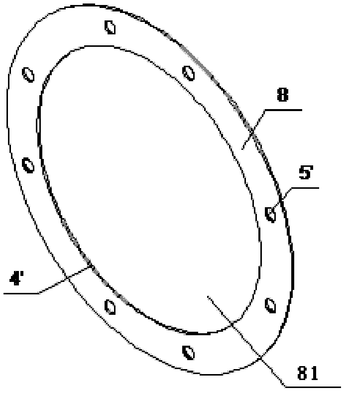
[0029] Between the two end plates 41 and 42, there are a plurality of rotor separators 8 made of non-magnetic materials. The rotor pole shoes 6 are independent of each other. The rotor pole shoes 6 and the rotor separators 8 are spaced apart. The rotor separators 8 Divide the rotor into a plurality of rotor units in the axial direction,...


PUM


Abstract

A radial rotor structure for a permanent magnet synchronous motor comprises a rotating shaft, a rotor core, permanent magnets, rotor pole shoes, a left end-plate and a right end-plate, wherein a plurality of rotor baffles are arranged between the two end-plates; the rotor pole shoes are independent of one another and distributed at intervals together with the rotor baffles; the rotor baffles axially divide a rotor into a plurality of rotor units; two end surfaces of the rotor pole shoes in each rotor unit are respectively clung to the end surfaces of the adjacent rotor baffles; one rotor pole shoe in each rotor unit corresponds to one permanent magnet; the rotor baffles are circular ring-shaped; the rotor core and the permanent magnets penetrate the circular through holes in the rotor baffles; a plurality of supporting wing plates are uniformly distributed on the outer side surface of the rotor core and are in clearance fit with the rotor baffles; and draw-in bolts penetrate the left end-plate, the rotor pole shoes, the rotor baffles and the right end-plate and axially lock the left and the right end-plates, as well as the rotor pole shoes and the rotor baffles, which are arranged between the left and the right end-plates. The radial rotor structure for the permanent magnet synchronous motor has the advantages of high mechanical strength and suitability for motors rotating at high speed.

Description

technical field [0001] The invention relates to a rotor structure of a radial permanent magnet synchronous motor, in particular to a permanent magnet built-in radial permanent magnet motor rotor for a permanent magnet traction motor of a high-speed railway train. Background technique [0002] The motor is an electromagnetic device that converts mechanical energy and electrical energy through the medium of a magnetic field. In order to establish the air-gap magnetic field necessary for electromechanical energy conversion inside the motor, there are two methods. One is to pass current through the motor windings to generate a magnetic field, such as ordinary DC motors and synchronous motors. This kind of electrically excited motor not only needs to have special windings and corresponding devices, but also needs to be continuously supplied with energy to maintain the current flow; the other is to generate a magnetic field by a permanent magnet. Due to the inherent characterist...

Claims


Application Information

Patent Timeline
Patent Type & Authority Patents(China)
IPC IPC(8): H02K1/27H02K1/28
Inventor 方攸同马子魁卢琴芬黄晓艳马吉恩张建承陈威
Owner ZHEJIANG UNIV
Why Eureka
Try Eureka