Winding support of single tooth winding for insulation motor

A winding and winding wire technology, applied in the field of insulation, holding and wiring, can solve problems such as mutual contact and short circuit

Active Publication Date: 2012-07-04
ROBERT BOSCH GMBH
View PDF9 Cites 18 Cited by
  • Summary
  • Abstract
  • Description
  • Claims
  • Application Information

AI Technical Summary

Problems solved by technology

The problem is that during this winding process the terminal wires of the individual stator coils cross each other and under certain circ...

Method used


Image

  • Winding support of single tooth winding for insulation motor
  • Winding support of single tooth winding for insulation motor
  • Winding support of single tooth winding for insulation motor

Examples


Embodiment Construction

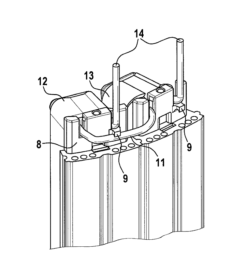
[0033] In order to insulate the winding wires of the stator tooth structure, a winding carrier is generally provided, which is often designed in two parts. The two winding carrier parts are attached from different sides to the stator tooth structure, which generally consists of metal laminations and is part of the stator.

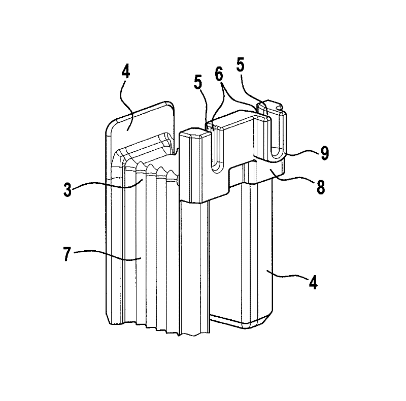
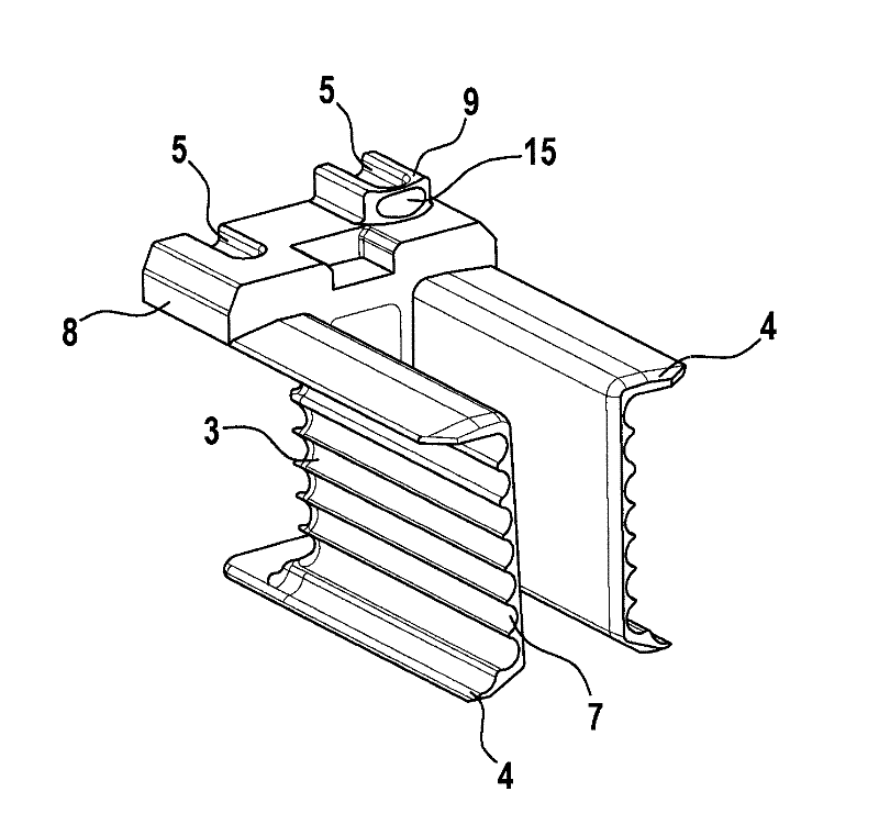
[0034] exist Figures 1a to 1d Various views of an embodiment for one half of the winding support are shown in . Such a winding carrier part 1 is preferably placed axially on the stator tooth structure to be wound from both sides, so that the magnetic material of the stator tooth structure is completely surrounded by the winding carrier. The winding carrier part 1 is preferably formed from an electrically insulating material such as, for example, plastic, especially thermoplastic. Thermosetting plastics or other electrically insulating materials may also be used.

[0035] The winding carrier or the winding carrier part 1 can be produced as a separate stru...


PUM


Abstract

The invention relates to a winding support part (1), in particular a winding support half body, which is arranged on the tooth structure of a motor. The winding support comprises a base portion (7) with the cross section thereof to be particularly U-shaped; a winding support collar (4) disposed at one end of the base part (7); a positioning structure (5) arranged on the winding support collar (4) and used for holding the terminal portion (11) of winding wires; and a guide element (9) used for guiding at least one terminal portion (11) of the winding wires.

Description

technical field [0001] The present invention relates to electrical machines, and more particularly to the insulation, retention and wiring of single-tooth windings on winding teeth in electrical machines. Background technique [0002] Electronically commutated electric machines generally have a stator with stator teeth. In the case of an inner rotor, the stator is generally of circular design and consists of one piece or of individual segments. In the latter case, the individual segments generally have a stator tooth structure which is first wound and then the wound individual segments are assembled to form a circular stator. The stator tooth structure of the individual sectors is usually wound with enamelled copper wire for applying the stator coils to the stator teeth. [0003] In order to avoid electrical short circuits between the winding wires and the steel sheets of the associated individual segments, insulating elements in the form of winding supports, which can be ...

Claims


Application Information

Patent Timeline
IPC IPC(8): H02K3/52
CPCH02K3/522
Inventor H.迈尔A.埃韦特T.格米恩德M.胡贝尔B.诺门森
Owner ROBERT BOSCH GMBH
Why Eureka
Try Eureka