Molding motor
A molding and housing technology, applied in the direction of electrical components, electromechanical devices, electric components, etc., can solve problems such as bearing damage
- Summary
- Abstract
- Description
- Claims
- Application Information
AI Technical Summary
Problems solved by technology
Method used
Image

Examples
Embodiment approach 1
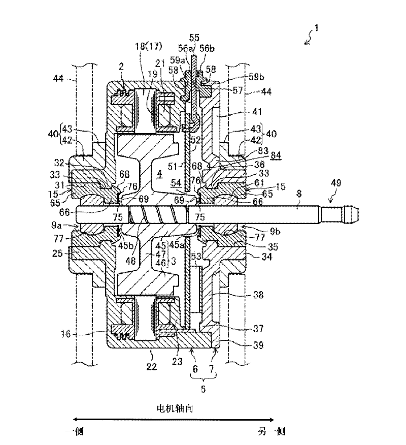
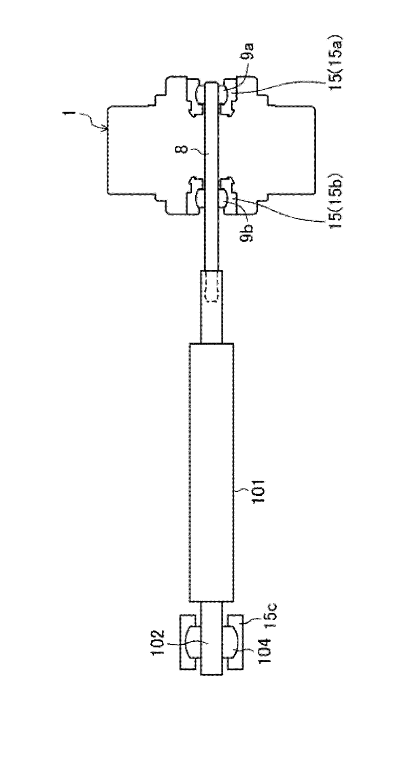
[0041] figure 1 One preferred example of the molded motor 1 (hereinafter simply referred to as the motor 1 ) of the embodiment of the present invention is shown. figure 2 One preferred example of a schematic diagram showing a state in which a molding motor is connected to a cross flow fan. Motor 1 is a brushless DC motor. The motor 1 is used to drive the cross-flow fan 101 of the air conditioner indoor unit 100 (refer to figure 2 ).
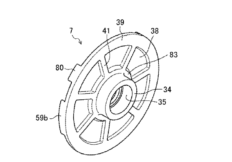
[0042] The motor 1 includes a cylindrical stator 2 . The motor 1 includes a motor housing 5 in which a housing space 4 for housing a rotor 3 is formed. The motor housing 5 includes a bottomed cylindrical (preferably bottomed cylindrical) case 6 with one axial side open, and a disc-shaped bracket cover 7 covering the opening side of the case 6 . The shape of the bracket cover 7 may not be a disc shape, but a shape that satisfies requirements. The case 6 is made of resin and covers and embeds the stator 2 . The housing 6 is integrally form...
Embodiment approach 2
[0077] Figure 11 A preferred example of Embodiment 2 is shown. The structure of the bearing holder 15, the bracket cover 7, and the housing 6 of the motor of Embodiment 2 differs from Embodiment 1. As shown in FIG. In addition, in the following embodiments, for substantially the same figure 1 The same constituent elements are denoted by the same reference numerals, and their detailed descriptions are appropriately omitted.
[0078] That is, in Embodiment 2, unlike Embodiment 1, the bearing holder 15 is formed in a cylindrical shape with a constant outer diameter. In addition, the anti-loosening groove 33 is not provided on the outer peripheral surface of the bearing holder 15 . On the other hand, a disk-shaped abutment plate portion 95 is formed at the motor-outer end portion of the hub portion 34 in the bracket cover 7 . The disc-shaped abutment plate portion 95 protrudes radially inward, and abuts on the end surface of the bearing holder 15 . Similarly, an abutment pla...
Embodiment approach 3
[0082] Figure 12 Embodiment 3 is shown, and the structure of the anti-vibration member 40 is different from Embodiment 1. FIG. That is, the motor 1 according to the third embodiment has the connecting rubber portion 99 which integrates the bearing holder 15 and the anti-vibration member 40 . As a result, the man-hours for assembling the motor and the number of parts are reduced, and the cost of the motor 1 is realized.
PUM
 Abstract
Description
Claims
Application Information
 - R&D Engineer
- R&D Manager
- IP Professional
- Industry Leading Data Capabilities
- Powerful AI technology
- Patent DNA Extraction
Browse by: Latest US Patents, China's latest patents, Technical Efficacy Thesaurus, Application Domain, Technology Topic.
© 2024 PatSnap. All rights reserved.Legal|Privacy policy|Modern Slavery Act Transparency Statement|Sitemap