Camera capable of achieving long-range shooting and super macro shooting

A camera and ultra-micro technology, applied in the field of cameras, can solve the problems of unable to observe distant targets, unable to obtain clear images, unable to install close-up mirrors or close-up rings, etc., to achieve the effect of expanding the shooting range

Inactive Publication Date: 2012-07-04
上海兴禄科技实业有限公司
View PDF4 Cites 10 Cited by
  • Summary
  • Abstract
  • Description
  • Claims
  • Application Information

AI Technical Summary

Problems solved by technology

[0003] Traditional camera modules use fixed optical lenses, manual or electric focus, and the closest camera distance is 0.2m-0.7m. When observing objects within 0.2m, it is impossible to obtain a clear image, so it is nec

Method used


Image

  • Camera capable of achieving long-range shooting and super macro shooting
  • Camera capable of achieving long-range shooting and super macro shooting
  • Camera capable of achieving long-range shooting and super macro shooting

Examples


Embodiment 1

[0034] The video camera of this embodiment capable of both telephoto shooting and ultra-macro shooting includes a camera module 100 and other components with the same structure as the existing video camera. see figure 1 , its camera module 100 includes a module housing 110, an optical lens assembly 120, and an imaging target surface assembly 130, and an optical lens assembly chute 111 parallel to the optical axis 200 of the camera module is arranged on the module housing 110, and An optical lens assembly slider (not shown) is arranged on the optical lens assembly 120, the optical lens assembly 120 is slidably arranged in the module housing 110, and the optical lens assembly slider on it is embedded in the optical lens assembly chute In 111, an optical lens assembly drive mechanism is provided in the module housing 110, so that the optical lens assembly 120 can move along the camera module optical axis 200 under the drive of the optical lens assembly drive mechanism, thereby ac...

Embodiment 2

[0037] The difference between the video camera of this embodiment that can realize both telephoto shooting and ultra-macro shooting is different from that of Embodiment 1 in that the driving mechanism of the optical lens assembly is different, and the rest is the same as that of Embodiment 1.

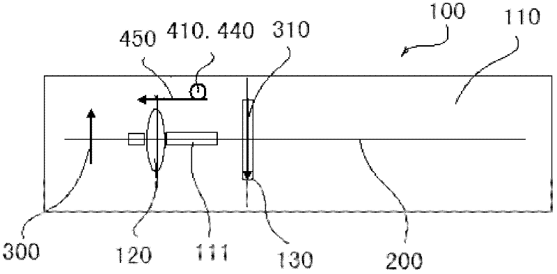
[0038] see figure 2 , the optical lens assembly driving mechanism of this embodiment includes an optical lens assembly driving servo motor 410 and an optical lens assembly driving gear 440 connected to the output shaft of the optical lens assembly driving servo motor 410 and an optical lens assembly driving rack 450, the optical The lens assembly driving rack 450 meshes with the optical lens assembly driving gear 440 on the one hand, and is connected with the optical lens assembly 120 on the other hand. The optical lens assembly driving servo motor 410 is controlled by the width of a pulse signal output by the signal generating unit, and the signal generating unit is controlled by the ...

Embodiment 3

[0040] The difference between the video camera of this embodiment that can realize both telephoto shooting and ultra-macro shooting is different from that of Embodiment 1 in that the driving mechanism of the optical lens assembly is different, and the rest is the same as that of Embodiment 1.

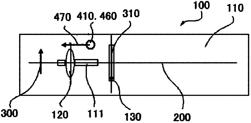
[0041] see image 3 , the optical lens assembly driving mechanism of this embodiment includes an optical lens assembly driving servo motor 410 and an optical lens assembly driving wheel 460 connected to the output shaft of the optical lens assembly driving servo motor 410 and an optical lens assembly driving link 470, the optical lens assembly One end of the lens assembly driving link 470 is eccentrically connected to the optical lens assembly driving wheel 460 , and the other end is connected to the optical lens assembly 120 . The optical lens assembly driving servo motor 410 is controlled by the width of a pulse signal output by the signal generating unit, and the signal generating un...


PUM


Abstract

The invention discloses a camera capable of achieving long-range shooting and super macro shooting, which comprises a camera module. The camera module comprises a module casing, an optical lens assembly and an imaging target surface assembly, wherein the optical lens assembly and the imaging target surface assembly are arranged in the module casing. The camera is characterized in that axial distance between the optical lens assembly and the imaging target surface assembly can be adjusted according to the axial distance between an object to be shot and the optical lens assembly. Due to the fact that the axial distance between the optical lens assembly and the imaging target surface assembly can be adjusted according to the axial distance between the object to be shot and the optical lens assembly, users only need to adjust a focusing key of the camera in order to shoot objects at any positions within a large range from infinity to 0.005m, clear images can all be observed on a television screen, and any devices are not required to be installed in front of and behind the lens. A shooting range of the camera is enlarged.

Description

technical field [0001] The present invention relates to the technical field of camera monitoring equipment, in particular to a camera capable of both long-distance shooting and ultra-macro shooting. Background technique [0002] The camera module currently used in cameras is mainly composed of a lens assembly, a base body, an imaging target surface, and a circuit board. Connection, the imaging target surface and the circuit board convert the collected optical signal into an electrical signal and send it out. [0003] Traditional camera modules use fixed optical lenses, manual or electric focus, and the closest camera distance is 0.2m-0.7m. When observing objects within 0.2m, it is impossible to obtain a clear image, so it is necessary to install A close-up lens or a close-up lens, but a camera with a close-up lens or a close-up lens cannot observe distant objects. Especially in some applications, it is impossible to add a close-up lens or a close-up ring. Contents of the...

Claims


Application Information

Patent Timeline
IPC IPC(8): H04N5/225H04N5/232G03B17/12
Inventor 齐哲杨齐海
Owner 上海兴禄科技实业有限公司
Why Eureka
Try Eureka