
Railway vehicle having front coupling cover

The technology of a rail vehicle and a coupling is applied in the field of rail vehicles and can solve the problems of the structural consumption of the driving device and the like

Active Publication Date: 2015-04-01
SIEMENS MOBILITY GMBH
View PDF3 Cites 0 Cited by
  • Summary
  • Abstract
  • Description
  • Claims
  • Application Information

AI Technical Summary

Problems solved by technology

[0004] A disadvantage of all these embodiments of rail vehicles with covers for front couplings of rail vehicles is that the construction of the drive of the locomotive can be considered complex.

Method used


Image

  • Railway vehicle having front coupling cover
  • Railway vehicle having front coupling cover
  • Railway vehicle having front coupling cover

Examples


Embodiment Construction

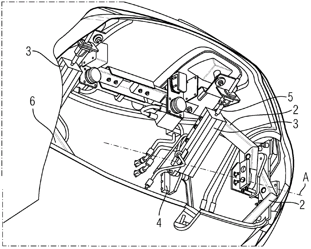
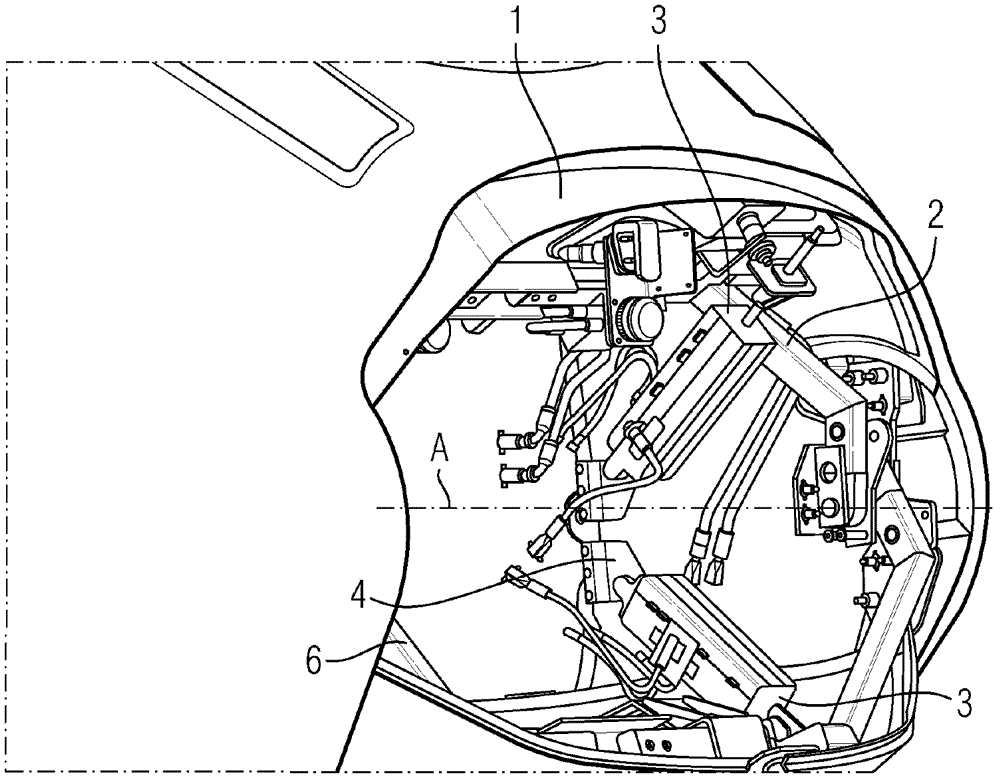
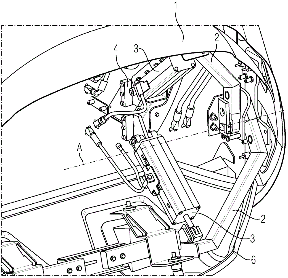
[0017] figure 1 A locomotive front part of a rail vehicle is shown, which has an upper locomotive hatch 1 that is displaceable between an open end position and a closed end position.

[0018] The movement of the upper bonnet 1 is determined by the guide arm 2 .

[0019] The guide arm 2 is mounted rotatably in the lateral region of the hood space, that is, rotates about an axis of rotation A which determines a purely rotational movement for the movement of the upper hood 1 . Since the axis of rotation A lies in the transverse or horizontal direction of the rail vehicle, the front hatch 1 moves between an upper position and a lower position, respectively corresponding to the closed or open end position.

[0020] The pneumatic cylinder 3 is articulated at its body-side end on a support 4 . For example a non-retractable front coupling (not shown) is located on the inside of the bracket 4 with respect to the vehicle. It can be seen that the piston rod 5 of the pneumatic cylinder...


PUM


Abstract

A railway vehicle has a cover for a front coupling of the railway vehicle. The cover is formed of at least one displaceable front hatch that can be displaced by a drive between an opened and a closed end position. A displacement of the at least one front hatch is guided such that the displacement takes place along a circular segment path about a rotary axis.

Description

technical field [0001] The invention relates to a rail vehicle with a cover for a front coupling of a rail vehicle, wherein the cover is formed by at least one movable locomotive hatch which can be opened and closed by means of a drive to move between the end positions. Background technique [0002] The cover panels for the front hatches of such rail vehicles serve above all optical and aerodynamic purposes. Usually two superimposed front hatches are provided, which can be moved into an open end position if required, so that additional vehicle components can be coupled by means of the front coupling. [0003] Examples of such vehicles of the prior art are ICE2 (Deutsche Bahn (DB) product series 402), ICE3 (DB product series 403 / 406) and TGVs of the French National Railways (SNCF). [0004] A disadvantage of all these embodiments of the rail vehicle with the cover plate for the front coupling of the rail vehicle is that the construction of the drive of the locomotive can be...

Claims


Application Information

Patent Timeline
Patent Type & Authority Patents(China)
IPC IPC(8): B61D17/06
CPCB61D17/06
Inventor 乌多·布雷梅坎普格哈德·施密特
Owner SIEMENS MOBILITY GMBH
Learn More