Optics with simultaneous variable correction of aberrations

A technology of optical elements and aberrations, applied in the directions of optical elements, optical components, optics, etc., can solve the problems of inefficient correction, inefficient fixed correction, etc.

Inactive Publication Date: 2012-07-04
AKKOLENS INT BV
View PDF10 Cites 8 Cited by
  • Summary
  • Abstract
  • Description
  • Claims
  • Application Information

AI Technical Summary

Problems solved by technology

[0006] In practice, however, most aberrations are variable and dependent on the position of the lens relative to the subject/imaging plane, meaning that, for example, fixed corrections become inefficien...

Method used


Image

  • Optics with simultaneous variable correction of aberrations
  • Optics with simultaneous variable correction of aberrations
  • Optics with simultaneous variable correction of aberrations

Examples


Embodiment Construction

[0059] Technical Information: We now proceed to further derive the formulas and explain the main invention, which as mentioned above enables the lens design in more detail. In the case of complementary structure variable third and higher order aberrations, expressed in terms of Zernike polynomials, and their linear combinations will be generated, all varying linearly with lateral deviation Δx. Use the following basis dip function S(x,y):

[0060] z = S ( x , y ) = P ∫ Σ q C q Z q ( x , y ) dx ,

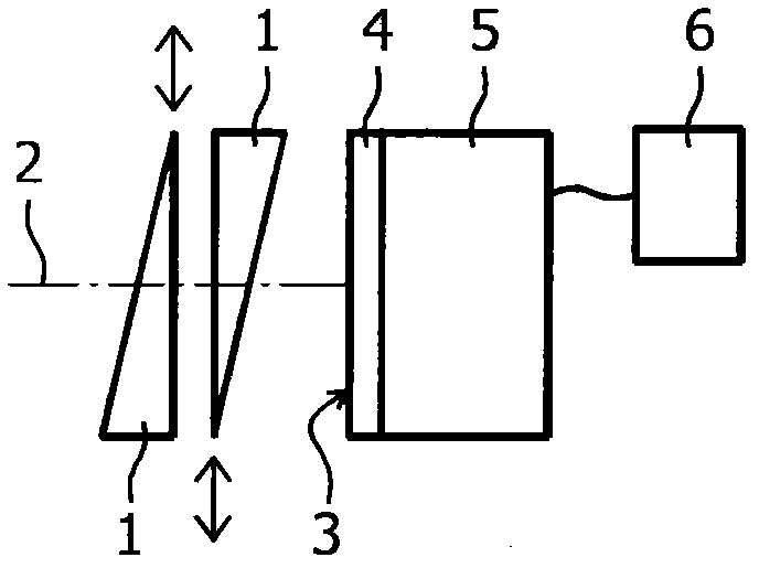
[0061] where P is a constant. For this example, basis functions can be added to a lens with two cubic elements:

[0062] z ...


PUM


Abstract

The invention refers to an optical system comprising at least two optical elements of which at least one is movable relative to the other in a direction perpendicular to the optical axis of the optical system, wherein the combination of optical elements is adapted to correct variable aberrations of at least two different orders simultaneously of which the degree of correction depends on the relative position of the optical elements. This optical system is adapted to correct aberrations which are variable and dependent on the position of the lens with respect to the subject/imaging plane. Further the optical system is adapted to correct aberrations varying along with defocus of the system. These aberrations may include second order aberrations, meaning defocus and astigmatism, third-order aberrations, meaning comas and trefoils, fourth-order aberrations, for example, spherical aberration, and further higher-order aberration terms.

Description

Background technique [0001] Conventional imaging lenses and lens assemblies are widely used in various optical devices and systems, such as cameras, to project final images onto photosensitive films or electronic image sensors. In this document, terms and definitions for imaging / optical systems are adopted from J.W. Goodman, Introduction to Fourier Optics, McGraw-Hill Co., Inc., New York, 1996 . A typical optical system includes various optical elements to correct various aberrations, mainly high-order monochromatic Zernik terms, such as spherical aberration and chromatic aberration. For example, monochromatic even-order aberrations can be conventionally corrected by additional refractive optical surface components, i.e., subcomponents with functional optical surfaces, according to [0002] z = S ( x , y ) = r 2 ...

Claims


Application Information

Patent Timeline
IPC IPC(8): G02B27/64G02B27/00G02B3/02G11B3/02G11B7/00F24J1/00F24V30/00
CPCG11B7/1356G02B27/0075F24J2/06G02C7/081G11B7/13927G02B27/0068G02B3/02G02B27/646F24S23/00
Inventor A·N·西蒙诺夫M·C·罗姆巴赫
Owner AKKOLENS INT BV
Why Eureka
Try Eureka