Transformer core

A transformer core and transformer technology, which is applied in the manufacture of inductors/transformers/magnets, parts of transformers/inductors, magnetic cores/yokes, etc., to reduce core noise, avoid repeated magnetization losses, and reduce electrical losses Effect

Inactive Publication Date: 2012-07-04
SIEMENS AG
View PDF9 Cites 2 Cited by
  • Summary
  • Abstract
  • Description
  • Claims
  • Application Information

AI Technical Summary

Problems solved by technology

This air gap increases the reluctance of the transformer laminations and thus the reluctance of the resulting transformer core

Method used


Image

  • Transformer core
  • Transformer core
  • Transformer core

Examples


Embodiment Construction

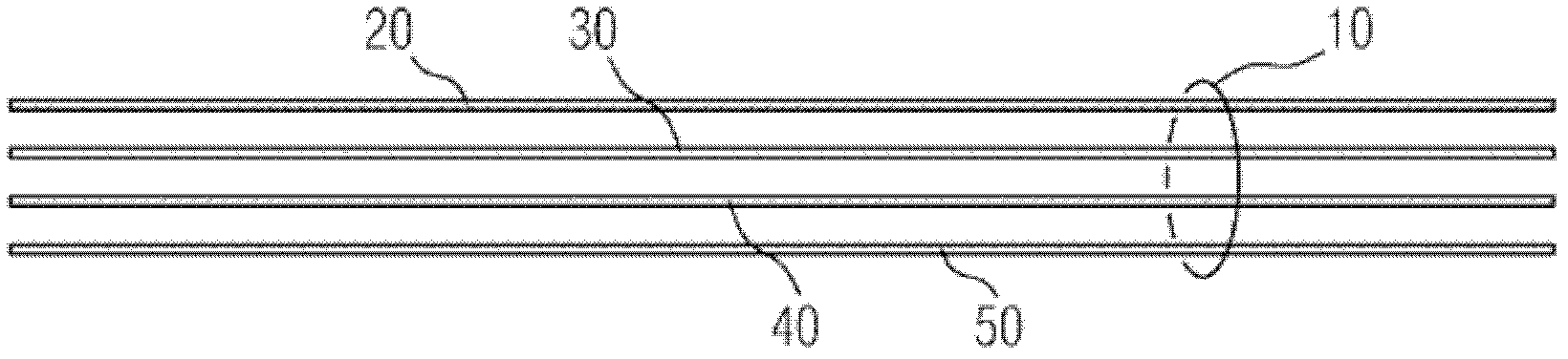
[0027] exist figure 1 A lamination stack 10 is seen in , which is formed by a plurality of transformer laminations, wherein, in figure 1 Four are shown as examples in , and are denoted by reference numerals 20 , 30 , 40 and 50 . The transformer laminations are made, for example, of a ferrosilicon alloy with soft magnetic properties, that is to say, for example, of so-called silicon steel sheet material.

[0028] The thickness of the transformer laminations is, for example, in the range of 200 to 600 microns. In order to achieve electrical insulation between the transformer laminations, the transformer laminations are preferably provided with a thin electrical insulation layer, which can have a thickness in the range of 1 micron to 5 microns, for example. For clarity, in figure 1 The electrically insulating layer is not shown in detail.

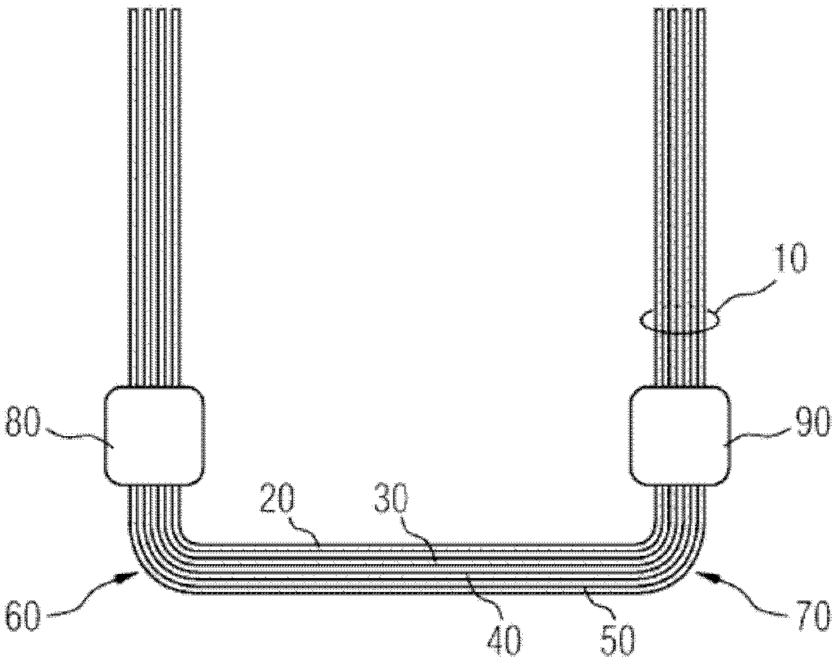
[0029] exist figure 2 A lamination stack 10 can be seen in , in which the transformer laminations 20 , 30 , 40 and 50 are each bent ...


PUM

PropertyMeasurementUnit
thicknessaaaaaaaaaa

Abstract

The invention relates to a method for producing a transformer core (200), among other things. According to the invention, adjacent plate edges are connected to one another by means of cold gas spraying using a material that can be magnetized. As a result, the magnetic flow can remain within the transformer plate without having to change to a neighboring transformer plate. Planar electrical eddy currents in the transformer plates can also be avoided and the electrical losses and the core noises can be reduced during operation of the transformer. By using a cold gas spraying method, bonding material can be formed on the basis of nanocrystalline or amorphous materials, for example. There is preferably one electrically isolating insert (300) provided between each of the two transformer plates after connecting the two plate edges of one of the transformer plates and before connecting the two plate edges of the next overlying transformer plate. According to the invention, the cold gas spray stream is thus prevented from hitting the underlying transformer plate when connecting the two plate edges of the overlying transformer plate.

Description

technical field [0001] The invention relates to a method having the features stated in the preamble of claim 1 . Background technique [0002] As for example in Siemens AG's literature "Leistungstransformatoren 10 bis100 MVA-der Garant für und (10 to 100MVA Power Transformers - Guarantee of Highest Quality and Reliability)" records that the transformer core is usually formed by transformer laminations. Due to structural reasons, it is usually not possible to actually butt the edges of the transformer laminations. Instead, the lamination edges are mostly separated from one another by a small air gap, which increases the reluctance of the transformer laminations and thus of the resulting transformer core. [0003] In order to reduce the influence of air gaps, so-called step laminations of transformer laminations are used in a known manner (as also known from the above-mentioned documents). In step laminations, the transformer laminations are arranged relative to each othe...

Claims


Application Information

Patent Timeline
Patent Type & Authority Applications(China)
IPC IPC(8): H01F3/02H01F27/245H01F41/02
CPCC23C24/04H01F27/2455H01F41/0233H01F3/02H01F27/245H01F41/02
Inventor M.厄特尔T.哈默F.海因里克斯多夫J.D.詹森U.克鲁格V.卢森O.斯蒂尔
Owner SIEMENS AG
Why Eureka
Try Eureka