
Rare earth permanent magnet

a permanent magnet, rare earth technology, applied in the direction of magnetic materials, magnetic circuits characterised by magnetic materials, magnetic bodies, etc., can solve the problems of high cost, low productivity, and disadvantages of providing protection layers, and achieve the effects of increasing the load of each step of cutting, grinding, adhesion and assembling, increasing its own load, and high cos

Active Publication Date: 2019-10-22
TDK CORPARATION
View PDF27 Cites 0 Cited by
  • Summary
  • Abstract
  • Description
  • Claims
  • Application Information

AI Technical Summary

Benefits of technology

[0009]However, when a magnet is divided, loads of each step of cutting, grinding, adhering, and assembling increase. In addition, when a protection layer such as resin coating is provided, a step of providing this protection layer increases its own load. Thus, the method disclosed in Patent Document 1 is disadvantageous in high cost and low productivity.
[0013]The rare earth permanent magnet according to the present invention has the above features, and thus can increase electric resistance of the entire magnet and prevent generation of eddy current.

Problems solved by technology

In addition, when a protection layer such as resin coating is provided, a step of providing this protection layer increases its own load.
Thus, the method disclosed in Patent Document 1 is disadvantageous in high cost and low productivity.

Method used


Image

  • Rare earth permanent magnet
  • Rare earth permanent magnet
  • Rare earth permanent magnet

Examples


examples

[0090]Hereinafter, the present invention will be described based on a more detailed example, but is not limited thereto.

Manufacture of Sintered Magnet

[0091]First, raw material metals of a sintered magnet were prepared, and a raw material alloy was fabricated using the raw material metals by a strip casting method so that a sintered magnet has a composition of 23.8 Nd-7.2 Pr-0.85 B-2.0 Co-0.4 Al-0.3 Cu-0.4 Ga-0.2 Zr-0.07 O-0.12 C-0.06 N-remaining part Fe (unit: mass %). Incidentally, contents of Nd, Pr, Fe, Co, Ga, Al, Cu, and Zr of each element were measured by a fluorescent X-ray analysis. The content of B was measured by ICP emission analysis. The content of O was measured by an inert gas fusion—non-dispersive infrared absorption method. The content of N was measured by an inert gas fusion—thermal conductivity method. The content of C was measured by a combustion in oxygen stream-infrared absorption method.

[0092]Next, hydrogen was stored in the obtained raw material alloy, and the...


PUM

PropertyMeasurementUnit
mass %aaaaaaaaaa
mass %aaaaaaaaaa
average grain diameteraaaaaaaaaa

Abstract

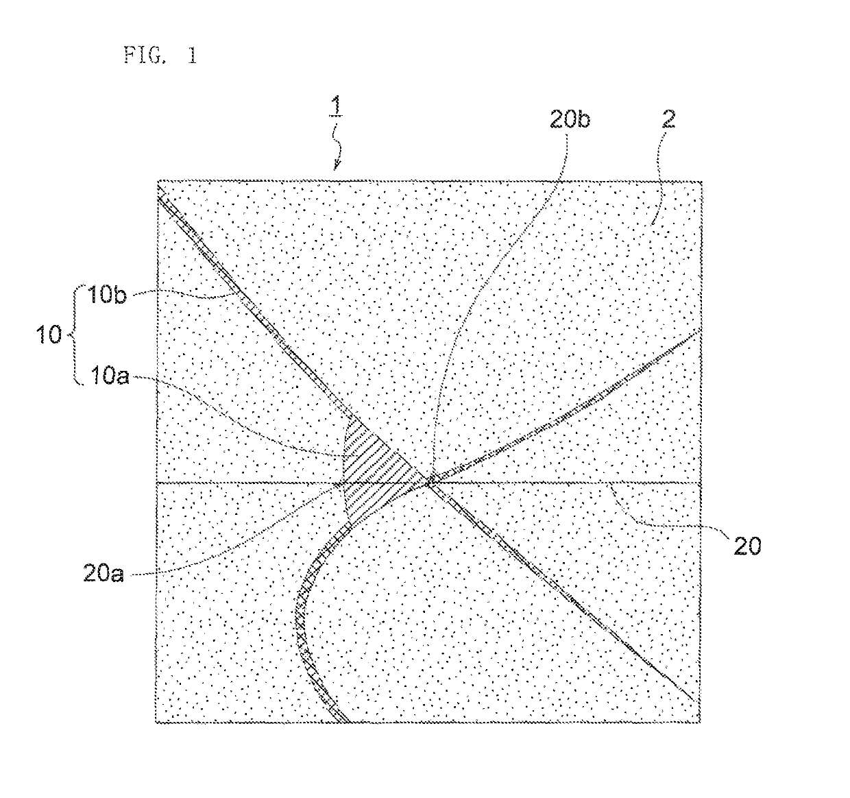
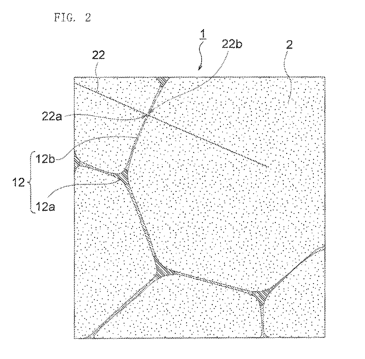
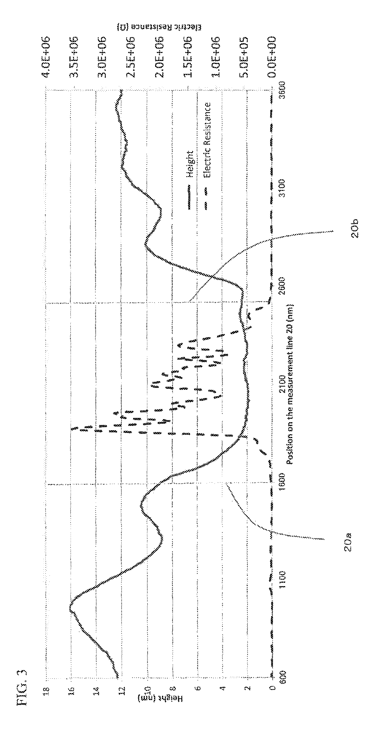
A rare earth permanent magnet includes a main phase composed of a main phase particle and a grain boundary present among a plurality of the main phase particles. The grain boundary includes a region whose electric resistance is higher than that of the main phase.

Description

BACKGROUND OF THE INVENTION[0001]1. Field of the Invention[0002]The present invention relates to a rare earth permanent magnet.[0003]2. Description of the Related Art[0004]Ferrite sintered magnets have been conventionally used as magnets for high-speed rotating motors. In accordance with demand in higher performance, however, motors using rare earth permanent magnets instead of the ferrite sintered magnets are widely used these days.[0005]In recent years, a rotation speed tends to further increase in accordance with higher efficiency of the motors, and a field weakening control method is commonly applied for controlling the motors.[0006]In the above two cases, a large eddy current flows through the magnet. A rare earth sintered magnet has an electric resistance that is smaller than an electric resistance of the ferrite sintered magnet. Thus, it is known that a large eddy current flows in case of using a rare earth sintered magnet for the motor, and that this magnet is demagnetized d...

Claims


Application Information

Patent Timeline
Patent Type & Authority Patents(United States)
IPC IPC(8): H01F1/053C22C38/00H01F1/08H01F1/057
CPCH01F1/0577C22C38/005H01F1/086H01F1/0536C22C38/001C22C38/002C22C38/06C22C38/10C22C38/14C22C38/16H01F1/0571H02K1/02
Inventor HIDAKA, TETSUYANAGAMINE, YUKIFUJIKAWA, YOSHINORI
Owner TDK CORPARATION
Learn More