Continuous cutting machine
A cutting machine and unit technology, applied in the direction of metal sawing equipment, sawing machine, metal processing equipment, etc., can solve the problems that affect the straight running accuracy, poor cutting straightness, material deviation, etc., to improve the cutting accuracy Effect
- Summary
- Abstract
- Description
- Claims
- Application Information
AI Technical Summary
Problems solved by technology
Method used
Image

Examples
Example Embodiment
[0022] Example 1:
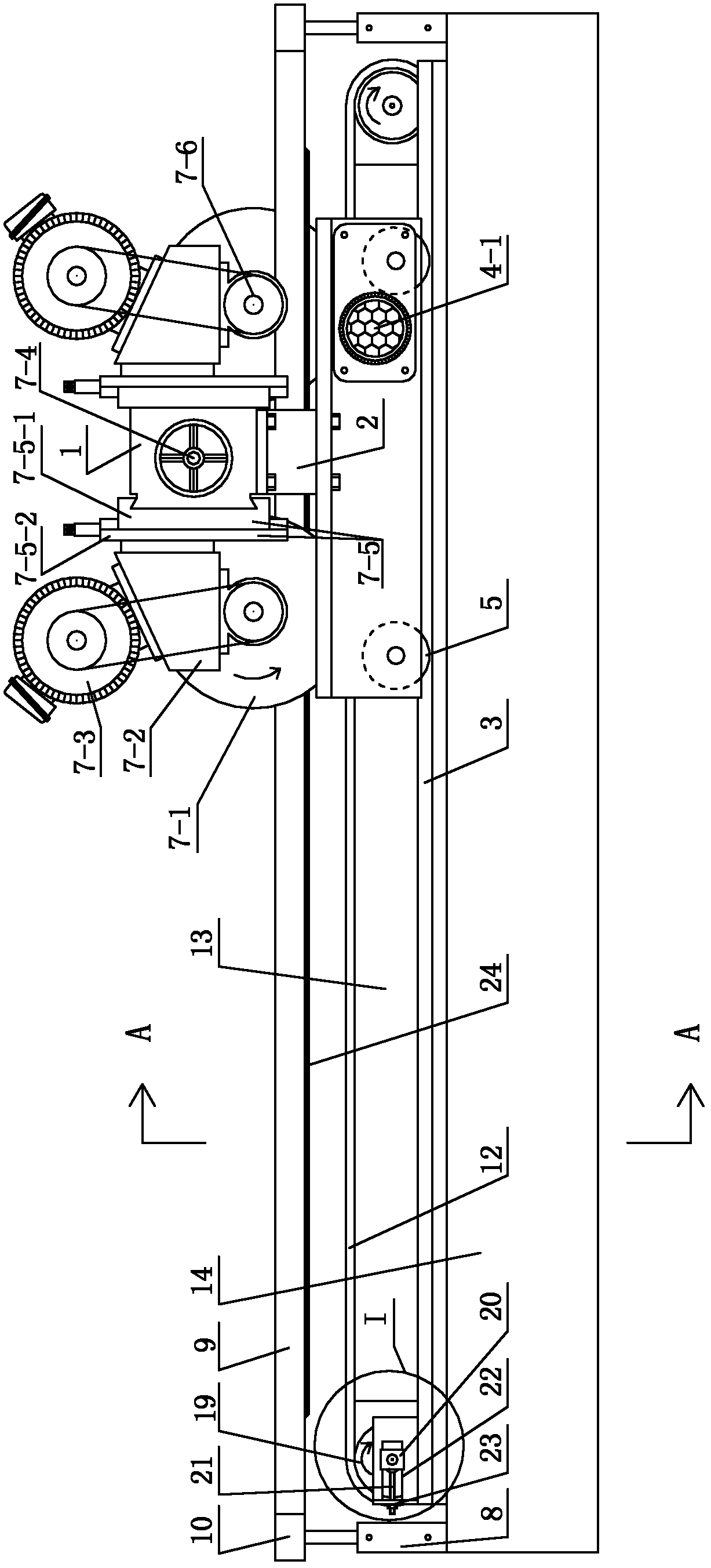
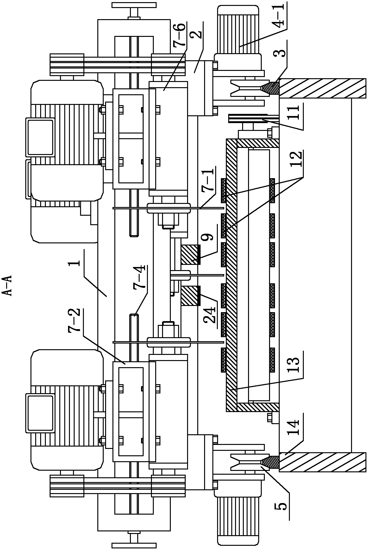
[0023] Such as Figure 1 to Figure 5 Shown is a schematic diagram of an embodiment of a continuous cutting machine provided by the present invention.
[0024] A continuous cutting machine, which is characterized in that it includes a conveying mechanism arranged in a transverse direction along the conveying direction, a trolley mechanism capable of reciprocating along the transverse direction, a cutting unit 7 fixed on the trolley mechanism and located above the conveying device, and A material pressing mechanism between the conveying mechanism and the cutting unit 7 and capable of controlling the lifting movement.
[0025] The trolley mechanism includes a trolley main beam 1 located above the material pressing mechanism and fixedly connected to the cutting unit 7, a pair of support beams 2 respectively arranged on both sides of the conveying mechanism and connected and fixed to the same side ends of the trolley main beam 1. A pair of guide moving components sepa...
Example Embodiment
[0039] Example 2:
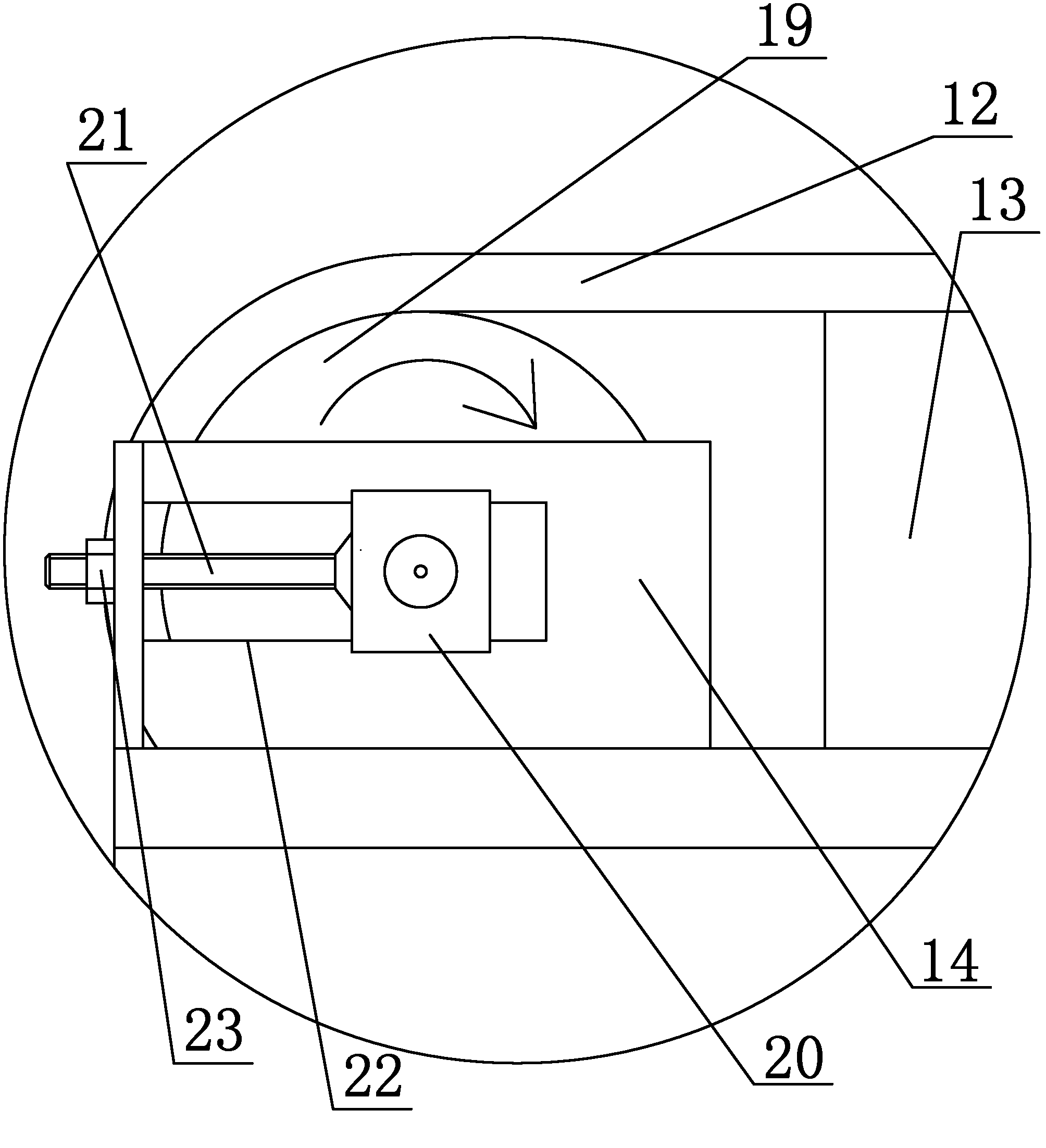
[0040] Such as Figure 6 to Figure 9 Shown is a schematic diagram of an embodiment of a continuous cutting machine provided by the present invention.
[0041] A continuous cutting machine, which is characterized in that it includes a conveying mechanism arranged in a transverse direction along the conveying direction, a trolley mechanism capable of reciprocating along the transverse direction, a cutting unit 7 fixed on the trolley mechanism and located above the conveying device, and A material pressing mechanism between the conveying mechanism and the cutting unit 7 and capable of controlling the lifting movement.
[0042] The trolley mechanism includes a trolley main beam 1 located above the material pressing mechanism and fixedly connected to the cutting unit 7, a pair of support beams 2 respectively arranged on both sides of the conveying mechanism and connected and fixed to the same side ends of the trolley main beam 1. A pair of guide moving components sep...
PUM
 Abstract
Description
Claims
Application Information
 - R&D
- Intellectual Property
- Life Sciences
- Materials
- Tech Scout
- Unparalleled Data Quality
- Higher Quality Content
- 60% Fewer Hallucinations
Browse by: Latest US Patents, China's latest patents, Technical Efficacy Thesaurus, Application Domain, Technology Topic, Popular Technical Reports.
© 2025 PatSnap. All rights reserved.Legal|Privacy policy|Modern Slavery Act Transparency Statement|Sitemap|About US| Contact US: help@patsnap.com