
Thee-dimensional link type variable-groove cutting arm

A bevel cutting, connecting rod type technology, applied in welding/cutting auxiliary equipment, auxiliary devices, gas flame welding equipment and other directions, can solve the problems of complex structure, the device cannot swing and rotate infinitely, and the design is cumbersome, etc., to achieve the transmission process. Simple, easy to manufacture, simple device design effect

Inactive Publication Date: 2014-05-07
发思特软件(上海)有限公司
View PDF6 Cites 0 Cited by
  • Summary
  • Abstract
  • Description
  • Claims
  • Application Information

AI Technical Summary

Problems solved by technology

[0003] The purpose of the present invention is to provide a transmission mechanism with a three-dimensional link type variable bevel cutting wall, which solves the problems that the existing device cannot swing and rotate infinitely, and the design is cumbersome and the structure is complicated.

Method used


Image

  • Thee-dimensional link type variable-groove cutting arm
  • Thee-dimensional link type variable-groove cutting arm
  • Thee-dimensional link type variable-groove cutting arm

Examples


Embodiment Construction

[0024] The specific implementation of the three-dimensional link type variable bevel cutting arm of the present invention will be given below with reference to the accompanying drawings.

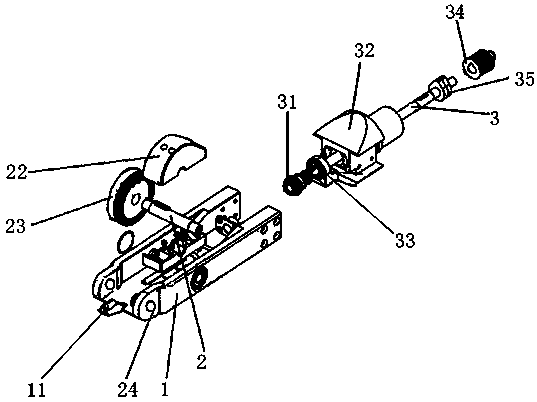
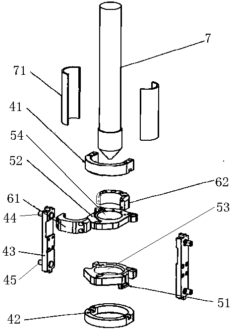
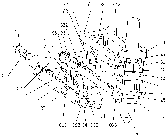
[0025] figure 1 It is an exploded schematic diagram of the driving arm in the three-dimensional connecting rod type variable bevel cutting arm of the present invention, figure 2 It is an explosion schematic diagram of the anti-collision device in the three-dimensional connecting rod type variable groove cutting arm of the present invention, image 3 For the schematic diagram of the three-dimensional link type variable bevel cutting arm of the present invention, please refer to figure 1 , figure 2 and image 3 shown. The three-dimensional link type variable bevel cutting arm includes a mechanical arm 1, and a driven shaft 2 is arranged on the mechanical arm 1. The driven shaft 2 is perpendicular to the mechanical arm 1, and a driven helical gear 23 is sleeved on the driven shaft. On th...


PUM


Abstract

The invention discloses a thee-dimensional link type variable-groove cutting arm, which is characterized in that a driven shaft is arranged on a mechanical arm, a driven helical gear is sleeved on the driven shaft, a driving helical gear is sleeved at the front end of a driving shaft, the driven helical gear is engaged with the driving helical gear, a driving shaft is perpendicular to the driven shaft to convert rotary torque into driving force, an upper ring sleeve and a lower ring sleeve are sleeved on the upper portion and the lower portion of a cutting head respectively, the lower portion of the cutting head is provided with a sleeve, a through hole of a lower flange is tightly connected with the sleeve, the upper ring sleeve, the lower ring sleeve and the flange are connected through two support rods, the upper end and the lower end of each support rod are respectively provided with an outwardly extending shaft, a link mechanism is connected with the shafts of the two support rods and two ends of the driven shaft, and the mechanical arm drives the link mechanism to move front and back through the driven shaft, so that the central point of the cutting head is unchanged.

Description

technical field [0001] The invention relates to a bevel cutting head device, in particular to a three-dimensional link type variable bevel cutting arm. Background technique [0002] The bevel cutting head is a device that uses numerical control signals to control the transmission mechanism for cutting. Such as the groove cutting device shown in the patent No. 01210356.X, which drives a pair of meshed gears to rotate through a motor, and a transmission shaft connected to a gear drives a helical gear to rotate, and the helical gear passes through the helical gear meshed with it. The tooth fan enables the parallel four-bar linkage mechanism connected with the beveling head to swing and rotate, and finally drives the beveling head to cut the steel plate. However, some of the current device products cannot swing and rotate infinitely, which is prone to winding. And some devices that can solve the problem of infinite swing and rotation are relatively complicated in design and un...

Claims


Application Information

Patent Timeline
Patent Type & Authority Patents(China)
IPC IPC(8): B23K7/10B23K37/02
Inventor 李浩伊莉
Owner 发思特软件(上海)有限公司
Learn More