Charging device with rotary chute

a charging device and rotary chute technology, applied in the direction of charging devices, charge manipulation, lighting and heating apparatus, etc., can solve the problems of high price of the charging device, large technical problems, and general heavy construction, and achieve the effect of simple and efficient mounting and disassembly of the chu

Inactive Publication Date: 2005-03-24
PAUL WURTH SA
View PDF9 Cites 14 Cited by
  • Summary
  • Abstract
  • Description
  • Claims
  • Application Information

AI Technical Summary

Benefits of technology

[0009] The chute is rotatable about its longitudinal axis between a first angular end position and a second angular end position, wherein the amplitude of rotation of the chute between its two end positions is preferably less than 180° and more preferably about 90°. It will be appreciated that—due to a small amplitude of rotation—it is possible to have a relatively simple drive for rotating the chute about its longitudinal axis.
[0014] It will be further appreciated that a simple an efficient solution for supporting the chute on the rotor is provided too. In accordance with this solution, the rotor comprises a rotatable support ring with an axis of rotation that defines an acute angle (α) with the vertical axis of rotation of the rotor. The chute has a tubular top end that is axially inserted into the rotatable support ring and secured to the latter, wherein the longitudinal axis of the chute is substantially coaxial with the axis of rotation of the rotatable support ring. In this embodiment, complementary bayonet connection means are advantageously associated with the tubular top end and the rotatable support ring for axially supporting the tubular top end of the chute in the rotatable support ring. It will be appreciated that this bayonet type connection allows easy mounting and dismounting of the chute.

Problems solved by technology

Indeed, the chute may have a cantilever length several meters, and due to heavy wear and heat protection, it is generally a very heavy construction.
It follows that the pivoting mechanism of the rotary chute must be conceived to transmit important pivoting moments onto the rotating chute, which creates a lot of technical problems and makes the charging device rather expensive.
It will be noted that the chute disclosed in this document is a very cumbersome device that is not really suited for distributing bulk material along a substantially spiral path onto a surface.

Method used


Image

  • Charging device with rotary chute
  • Charging device with rotary chute
  • Charging device with rotary chute

Examples


Embodiment Construction

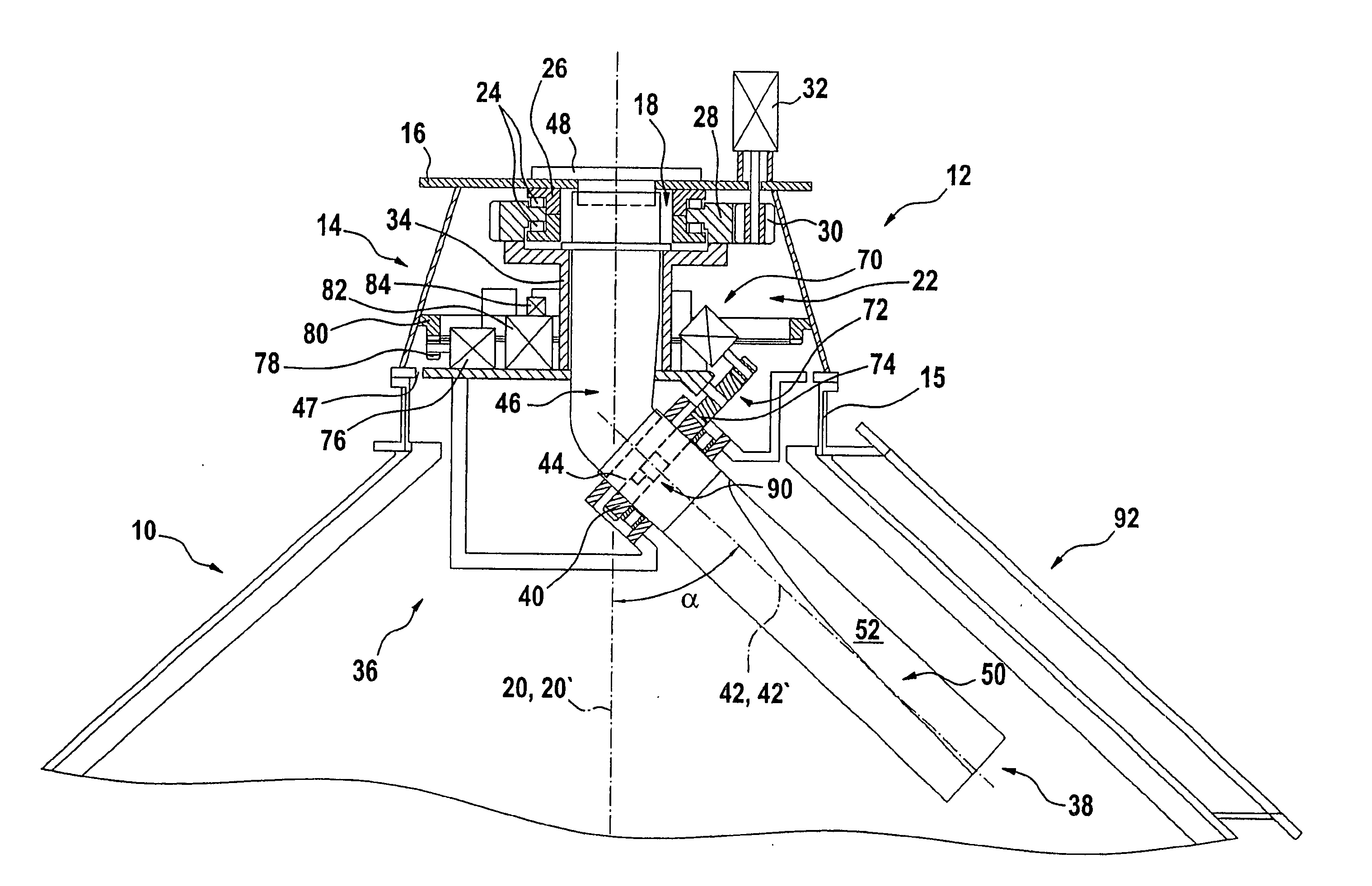
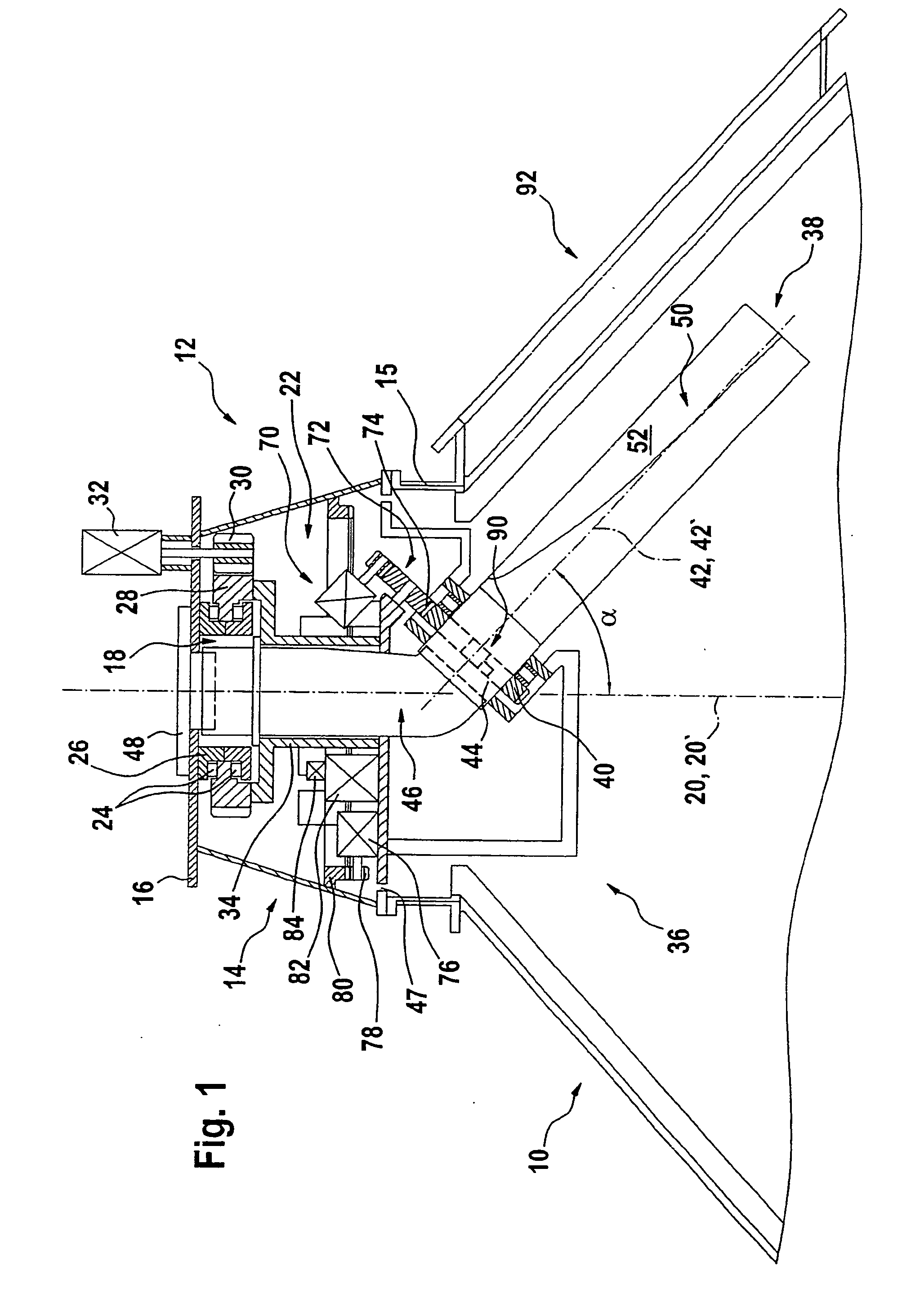
[0022] In FIG. 1, reference number 10 identifies a shaft furnace, as e.g. a blast furnace, that is equipped with a charging device 12 in accordance with the present invention. This charging device 12 comprises a support structure conceived as a housing 14, which is connected with its open bottom end to a top flange 15 of the shaft furnace 10. At its top end, the housing 14 is closed by a top plate 16 with an opening 18 centred on the vertical central axis 20 of the shaft furnace 10.

[0023] Reference number 22 globally identifies a rotor. The latter is supported inside the housing 14 by means of big diameter roller bearings 24. The latter are connected between the top end of the rotor 22 and a support flange 26 of the top plate 16, so that the rotor 22 has an axis of rotation 20′ that is substantially coaxial to the vertical central axis 20 of the shaft furnace 10. The top end of the rotor 22 is furthermore equipped with a gear ring 28. A pinion 30 of a motor 32, which is mounted out...


PUM

PropertyMeasurementUnit
angleaaaaaaaaaa
rotationaaaaaaaaaa
axis of rotationaaaaaaaaaa

Abstract

A charging device for bulk material comprises a rotor having a substantially vertical axis of rotation a first drive for rotating the rotor and a chute supported by the rotor so as to be rotated with the latter. The chute can be rotated about its longitudinal axis. Its concavely curved sliding surface has a width that is diminishing from the top end to the bottom end of the chute, so that it is possible to vary the location where bulk material sliding down the chute channel leaves the latter by rotating the chute about its longitudinal axis.

Description

FIELD OF THE INVENTION [0001] The present invention relates to a charging device with a rotary chute. BACKGROUND OF THE INVENTION [0002] Charging devices with rotary chutes are inter alia used in shaft furnaces (such as e.g. modern blast furnaces) for providing a more or less uniform distribution of bulk material onto a charging surface inside the furnace. The chute defines for the charging material a chute channel with a concavely curved sliding surface. It is suspended in a cantilever manner from a rotor having a substantially vertical axis of rotation and can be pivoted on this rotor about a substantially horizontal suspension axis to change the inclination of the chute channel. By rotating the rotor about its vertical axis of rotation and simultaneously varying the inclination of the chute by means of a rotating pivoting mechanism, it is consequently possible to distribute the bulk material along a substantially spiral path onto a charging surface in the furnace. [0003] Charging...

Claims


Application Information

Patent Timeline
Patent Type & Authority Applications(United States)
IPC IPC(8): B65G11/20B65G11/00B65G69/04C21B7/20F27D3/10
CPCC21B7/20C21B7/205B65G69/0441C21B5/001F27B1/20F27D3/10
Inventor GORZA, ROBERTTHILLEN, GUY
Owner PAUL WURTH SA
Why Eureka
Try Eureka