Feeding compaction device of silage harvesting machine

A compacting device and technology for silage, which are applied in harvesters, agricultural machinery and implements, applications, etc., can solve the problems of untidy arrangement of straws, affect the quality of chopping, affect the quality of silage, etc. The effect of improving the cutting effect and improving the feeding efficiency

Inactive Publication Date: 2015-02-04
内蒙古长明机械股份有限公司
View PDF5 Cites 15 Cited by
  • Summary
  • Abstract
  • Description
  • Claims
  • Application Information

AI Technical Summary

Problems solved by technology

When harvesting, the density and height of the crops are not uniform, and when entering the feeding inlet, the straw cannot be arranged neatly, which affects the quality of chopping, and it is easy to form a blockage in the feeding inlet, and the length after cutting is different, and the longer straw Livestock do not like to eat, which affects the quality of silage
The general feeding mechanism either adopts several feed rollers arranged vertically or several feed rollers arranged horizontally, but they are all fixed and rotating rollers, and have no compaction function; some silage machine feeding devices also have Floating roller device, but due to the difficulty of driving the floating roller, the driven floating roller is often used. The floating roller itself has no power transmission, which reduces the efficiency of crop feeding. Some silage machine floating rollers are driven by cross shafts, and at the same time realize the floating roller floating and rotating, but the cross shaft transmission structure is complex and difficult to maintain

Method used


Image

  • Feeding compaction device of silage harvesting machine
  • Feeding compaction device of silage harvesting machine
  • Feeding compaction device of silage harvesting machine

Examples


Embodiment Construction

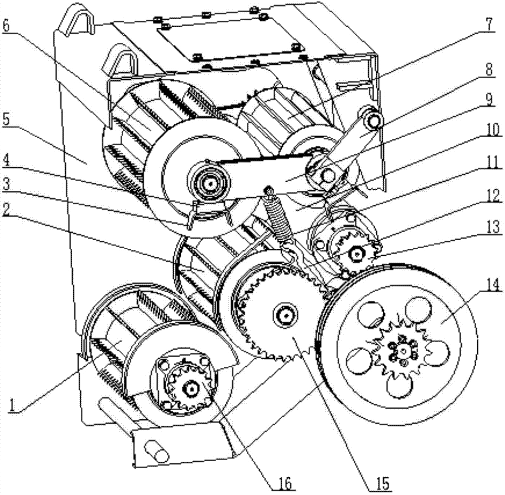
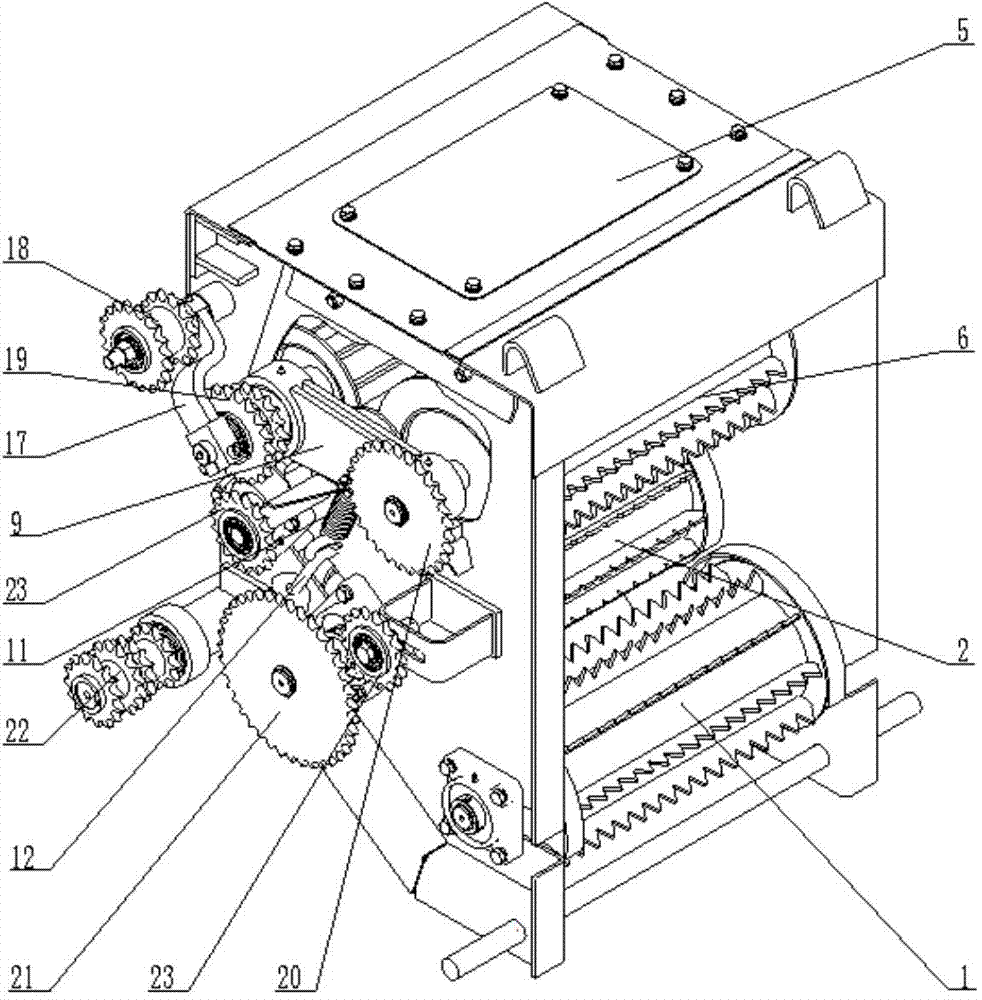
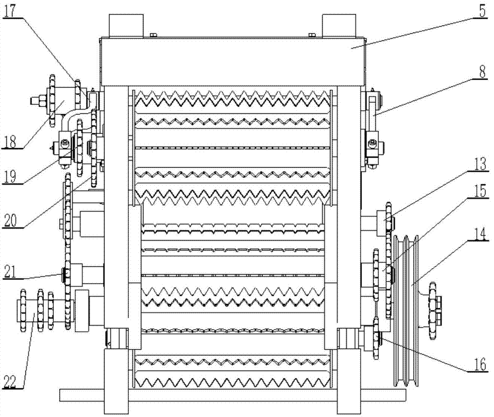
[0018] Such as Figure 1 to Figure 5 It can be seen that the device is composed of a frame (5), a floating rotating roller, a fixed rotating roller, a connecting device, a tensioning device, and a power transmission device; the fixed rotating roller is the first fixed rotating roller (1), and the second fixed rotating roller. Rotating rollers (2), three fixed rotating rollers (10), wherein serrated teeth are welded on the first fixed rotating roller and the second fixed rotating roller, and the three fixed rotating rollers are arranged in steps and fixed on the frame (5 ) of the bottom; said floating turning rollers are the first floating turning rollers (6), two floating turning rollers (7) connected to the top of the frame (5) through the connection devices on both sides respectively, and the first floating turning rollers (6) ) is welded with serrated roller teeth; the specific structure is that the right side of the first floating rotating roller (6) and the second floatin...


PUM


Abstract

The invention provides a feeding compaction device of silage harvesting machine. The feeding compaction device consists of a framework, floating rotating rollers, fixed rotating rollers, a connecting device, a tensioning device and a power transmission device, wherein the three fixed rotating rollers are in step type arrangement and are fixedly arranged at the lower part of the framework, the floating rotating rollers are connected onto the upper part of the framework, the two floating rotating rollers and the three fixed rolling rollers are respectively in transverse arrangement, the two floating rotating rollers and the lower part of the framework are provided with the tensioning device, a power input wheel is respectively connected with the two floating rotating rollers and the three fixed rotating rollers through the transmission device, and a bent connecting rod is adopted for power transmission between the two floating rotating rollers. In a straw feeding process, crops are tightly compacted through the tensioning force of the tensioning device and the self weight of the floating rollers. A floating connecting rod mechanism arranged at the right side of the floating rotating rollers is made into a floating bent connecting rod mechanism, and the chain transmission power input is favorably realized, so that the floating rotating rollers are also power input rotating rollers, and the feeding efficiency is improved. The transmission process is simplified, and in addition, the fault rate is reduced.

Description

technical field [0001] The invention relates to an agricultural machine, in particular to a feeding and compacting device for a silage harvester. Background technique [0002] At present, most of the crops in northern my country are ripe once a season, so most of the livestock are fed with hay in autumn and winter, and there is a lack of fresh green forage. Silage is a kind of roughage obtained by chopping green feed with a moisture content of 65%-75%, and then fermenting it with anaerobic lactic acid bacteria under airtight and hypoxic conditions. Silage is soft and juicy, has good palatability, is rich in nutrition, and is good for long-term storage. It is an excellent feed source for livestock. [0003] With the continuous development of animal husbandry and the widespread use of mechanized operations, the requirements for silage harvesters have also increased accordingly. The self-propelled silage harvesters currently in use generally consist of headers, feeding mechani...

Claims


Application Information

Patent Timeline
Patent Type & Authority Applications(China)
IPC IPC(8): A01D57/01
Inventor 郑伟兵张明康秀川李绍华李文静贾文华
Owner 内蒙古长明机械股份有限公司
Why Eureka
Try Eureka