Guide-cutting plate of a cutting wheel for a paper shredder

a cutting wheel and paper shredder technology, applied in the field of paper shredder cutting wheel guide cutting sheet, can solve the problems of affecting the shredder's shredding effect, affecting the normal operation of the paper shredder in a severe condition, and affecting the safety of operation, so as to improve the shredding effect and improve the safety of operation.

Inactive Publication Date: 2010-07-13
LO EMILY
View PDF12 Cites 5 Cited by
  • Summary
  • Abstract
  • Description
  • Claims
  • Application Information

AI Technical Summary

Benefits of technology

[0005]Accordingly, the primary object of the present invention is to provide a guide-cutting plate for a cutting wheel for a paper shredder, which is able to overcome a push-open phenomenon that may occur when too many paper sheets are rolled into cut-openings of rotary cutting wheels, thereby facilitating a normal operation of the paper shredder and improving a paper shredding effect. In addition, through a rabbet of a guide-cutting plate to latch two side walls of a strip-shape aperture on a face cover, a phenomenon that the strip-shape aperture is pushed open by feeding into too many paper sheets can be prevented, thereby satisfying a safety regulation and largely improving safety of operation.

Problems solved by technology

This push-open phenomenon will not only enable the blades of the cylindrical rotary cutting wheels to be fractured very easily, such that a shredding effect of the paper shredder will be affected; but also will affect a normal operation of the paper shredder in a severe condition.
However, the strip-shape aperture on the face cover of the paper shredder will be pushed open when too many paper sheets are fed in; and if the strip-shape aperture is pushed open excessively, a more significant safety concern will be formed and a safety regulation cannot be satisfied either.

Method used


Image

  • Guide-cutting plate of a cutting wheel for a paper shredder
  • Guide-cutting plate of a cutting wheel for a paper shredder
  • Guide-cutting plate of a cutting wheel for a paper shredder

Examples


Embodiment Construction

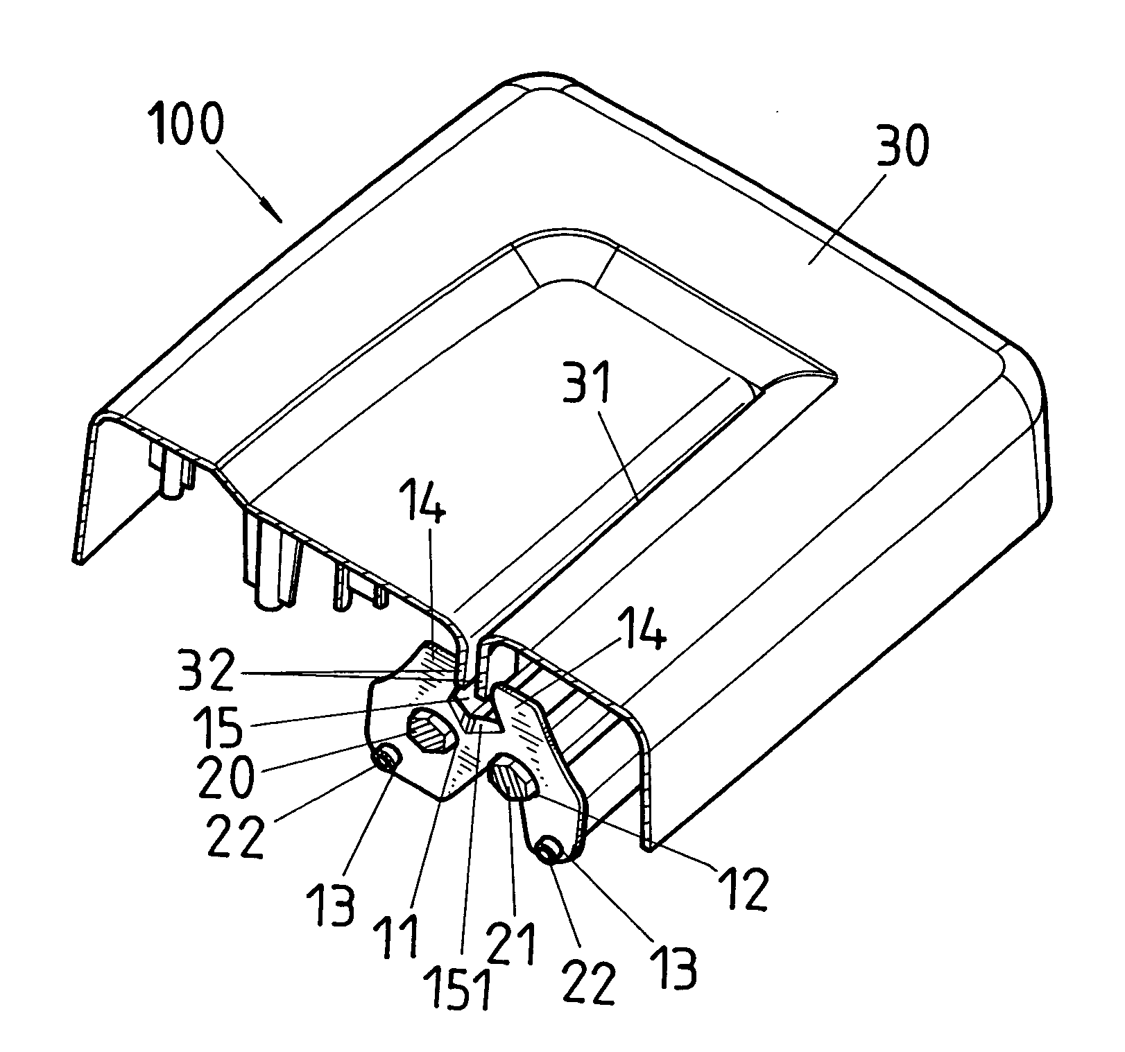
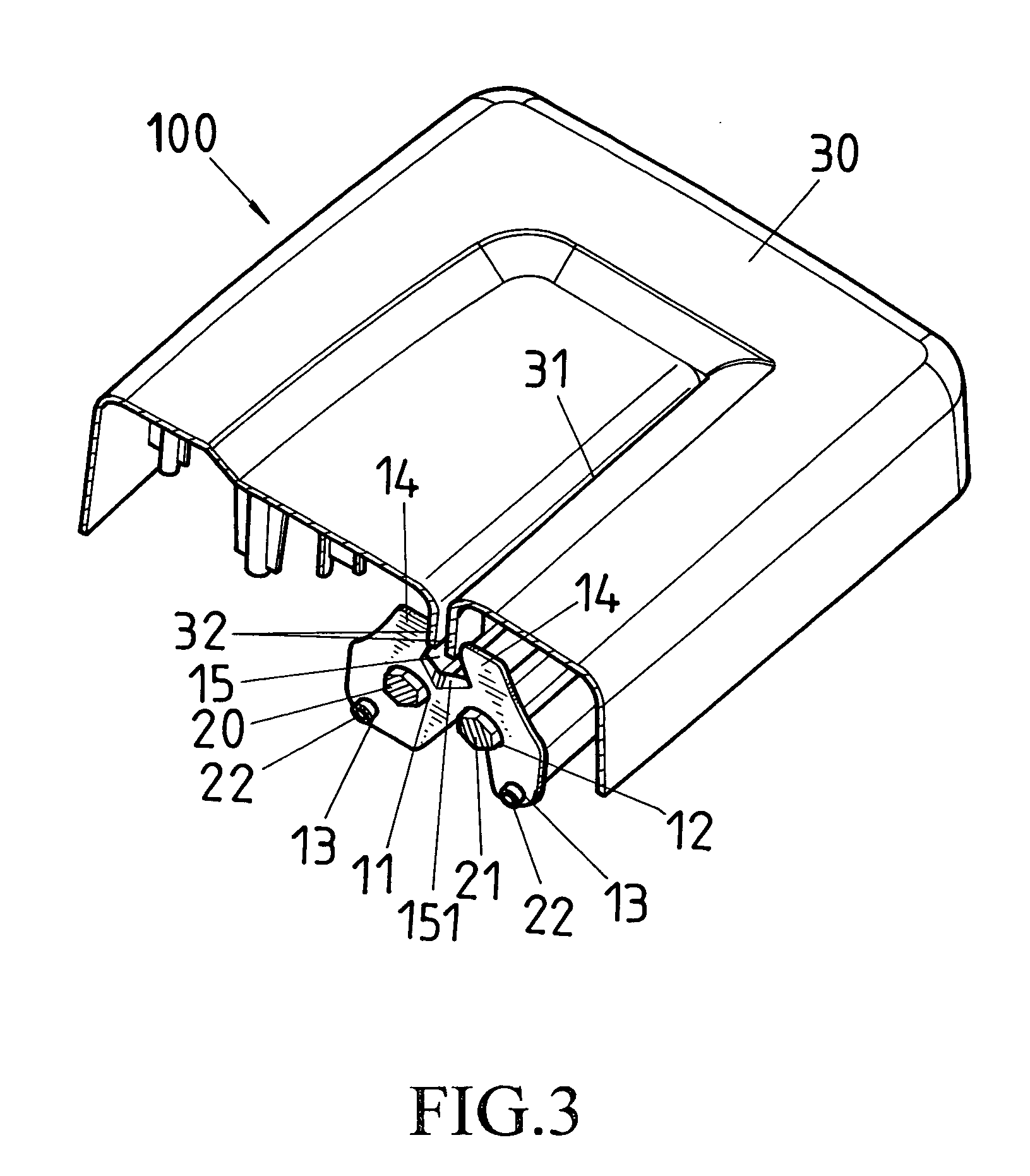
[0017]As shown in FIG. 3, a metallic guide-cutting plate 10 is mounted on a paper shredder head having two parallel cylindrical rotary cutting wheels on blade shafts 20,21 and two fixing rods 22 positioned in proximity of said blade shafts 20,21 with a shredder cover 30 having a longitudinal strip-shape aperture above a centerline (or nip, see FIG. 4) of the two parallel cylindrical rotary cutting wheels installed on the blade shafts 20,21.

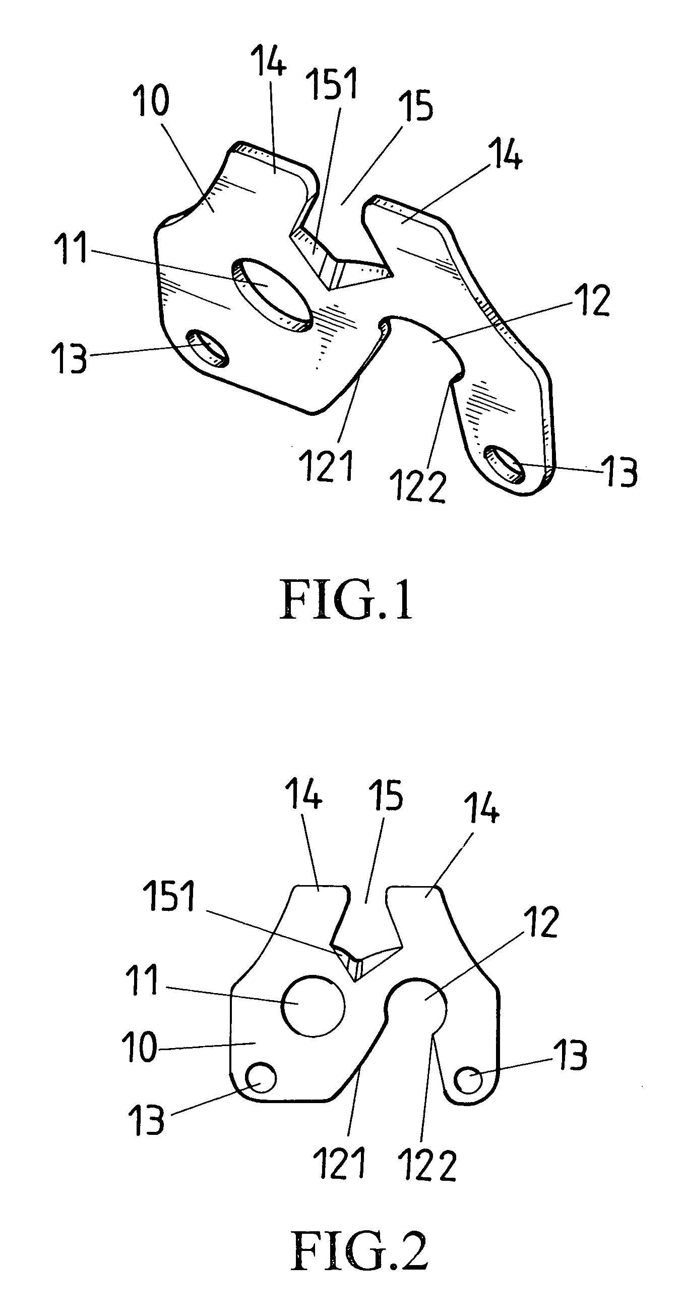
[0018]Referring to FIG. 1 and FIG. 2, on two sides of a centerline of a metallic guide-cutting plate 10 are opened respectively with blade shaft transfix holes 11, 12 corresponding to a spacing of blade shafts of two parallel cylindrical rotary cutting wheels, and an opening end of one blade shaft transfix hole 12 is a blade shaft latch-in mouth 121, with a neck part 122 at a middle section; below the two blade shaft transfix holes 11,12 respectively, the guide-cutting plate 10 is opened with fixing rod transfix holes 13 corresponding to a spacing...


PUM


Abstract

A guide-cutting sheet of a cutting wheel for a paper shredder is characterized in that two sides of a centerline of a planar linear guide-cutting sheet are opened respectively with blade shaft transfix holes corresponding to a spacing between the blade shafts of two parallel cylindrical rotary cutting wheels; below or above two blade shaft transfix holes are opened respectively with fixing rod transfix holes, corresponding to a spacing between two fixing rods; the centerline part above two blade shaft transfix holes is opened with a rabbet which can be latched at two aperture walls of a strip-shape aperture on a face cover; and a bottom of the rabbet is provided with a concaved knife-edge which can cut off paper sheets.

Description

BACKGROUND OF THE INVENTION[0001]a) Field of the Invention[0002]The present invention relates to a guide-cutting sheet of a cutting wheel for a paper shredder[0003]b) Description of the Prior Art[0004]Cutting wheels of an ordinary paper shredder are constituted by two cylindrical rotary cutting wheels that rotate in opposite directions (clockwise and counterclockwise); whereas, the cylindrical rotary cutting wheel is assembled by a blade shaft and a plurality of blades that are sheathed on the blade shaft and are separated with each other with a gasket. The two cylindrical rotary cutting wheels are placed side by side, and installed parallel on a blade rack, with every blade, which is aligned on one of the two cylindrical cutting wheels, being intersected with each other to form a plurality of cut-openings. As the rotary cutting wheels should bear with certain pressure when shredding paper sheets that are fed in, a certain requirement for intensity and rigidity of the two cutting wh...

Claims


Application Information

Patent Timeline
Patent Type & Authority Patents(United States)
IPC IPC(8): B02B7/02B02C23/00
CPCB02C18/0007B02C18/142B02C2018/0046B02C2018/168
Inventor LO, EMILY
Owner LO EMILY
Why Eureka
Try Eureka