Novel combined harvester shredding device

A technology of shredding device and harvester, applied in the direction of harvester, cutter, etc., can solve the problems of large handover distance of fixed knives, small diameter of rotating cylinder, large number of fixed knives, etc. Low power, good weeding effect

Inactive Publication Date: 2014-07-23
曾联
View PDF6 Cites 5 Cited by
  • Summary
  • Abstract
  • Description
  • Claims
  • Application Information

AI Technical Summary

Problems solved by technology

This structure has a certain effect on the shredding of straw, but it also has its shortcomings
1. The fixed knife is installed under the moving knife, and the moving knife rotates counterclockwise, and the grass is thrown to the vibrating screen to easily form air convection, resulting in poor cleaning effect
2. The structure of the fixed knife is single. The toothed fixed knife harvests rice and is easy to entangle grass. The toothless fixed knife harvests wheat.
3. The diameter of the rotating cylinder of this structure is small, the number of moving and fixed knives is large (20-24 moving and fixed knives each), the handover distance of moving and fixed knives is large, the handover area is also large, and the power consumption of grass cutting operation is large, which is easily affected Harvesting effect
4. The number of moving and fixed knives is large, the corresponding maintenance cost is high, and maintenance is time-consuming
For example, the application number: 200920283859.2 disclosed "the shredding device with throwing function matched with the combine harvester" includes a shredding knife shaft arranged on the shredding device box, and a shredding power transmission belt connected to the outer end of the shredding knife shaft. The lower end of the shredding device box supports the throwing impeller, and its structure only adds a throwing impeller, which still has the above-mentioned problems.

Method used


Image

  • Novel combined harvester shredding device
  • Novel combined harvester shredding device
  • Novel combined harvester shredding device

Examples


Embodiment 1

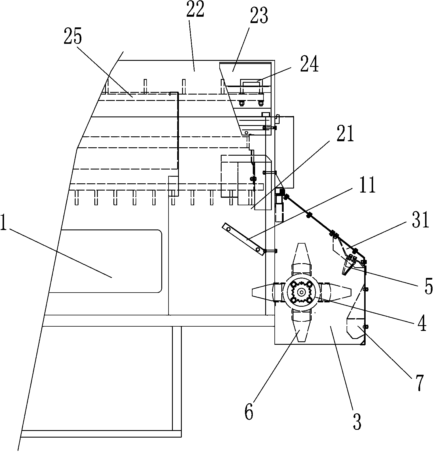
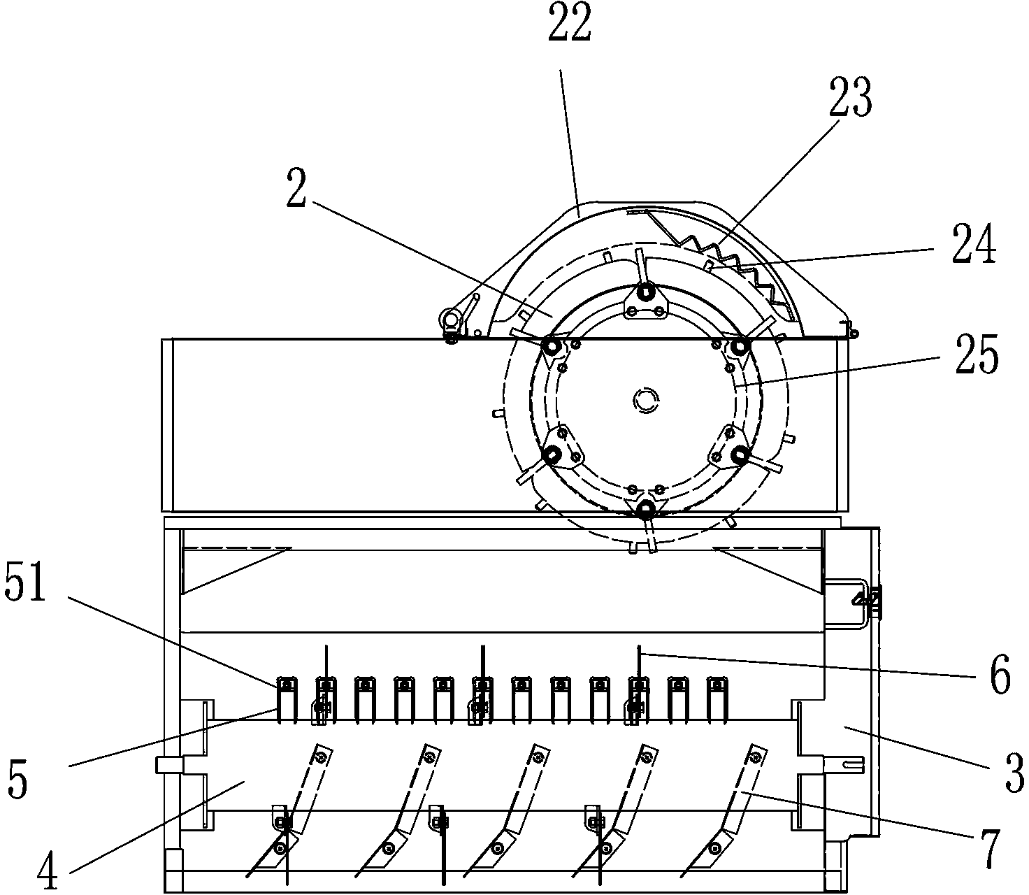
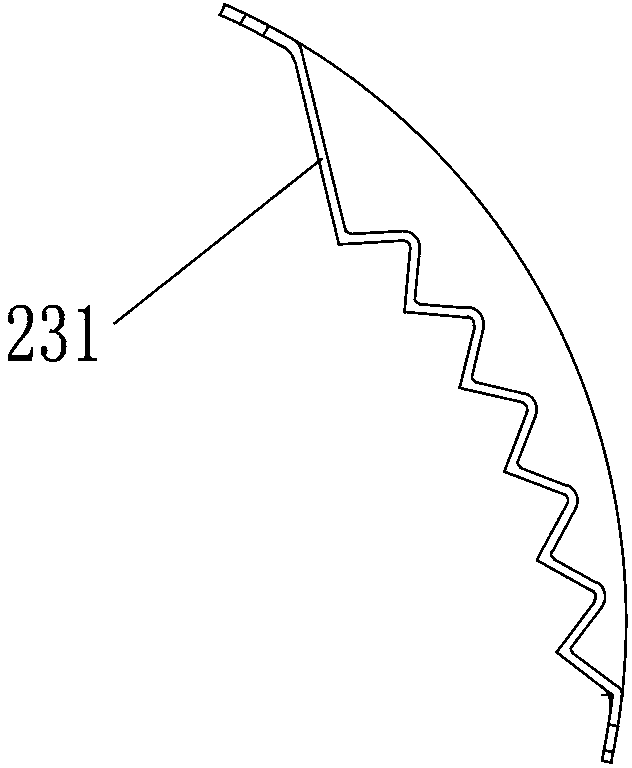
[0039] A new combined harvester chopping device, the harvester includes a frame 1 and a threshing drum 2 arranged on the top of the frame 1, the threshing drum 2 includes a top cover 22 and a rack 25, the threshing drum 2 The bottom of the end is provided with a discharge port 21, and the chopping device includes a broken grass washboard 23 arranged at the rear end of the top cover 22, a tooth 24 arranged on the rack 25 and matched with the broken grass washboard 23, and a tooth 24 arranged at the discharge port 21. The grass cutter assembly below, the grass cutter assembly includes a discharge rack 3 arranged at the rear end of the frame 1, a frame cover 31 arranged on the discharge frame 3, a discharge chamber positioned under the frame cover 31, The discharge drum 4 arranged on the discharge rack 3 and located in the discharge chamber, the fixed knife 5 and the movable knife 6 arranged on the discharge rack 3 and the discharge drum 4, the discharge port 21 and the discharge ...

Embodiment 2

[0045] The difference from the above implementation is that there are 15 fixed knives, and 5 rows of movable knives are evenly distributed on the surface of the discharge drum, and each row has 3 movable knives, and the movable knives on adjacent rows are arranged alternately. The handover distance between the moving knife and the fixed knife is 20mm, and the diameter of the discharge drum is 160mm.

Embodiment 3

[0047] The difference from the above implementation is that there are 10 fixed knives, and 5 rows of movable knives evenly distributed on the surface of the discharge drum, with 2 movable knives in each row, and the movable knives on adjacent rows are arranged alternately. The handover distance between the moving knife and the fixed knife is 30mm, and the diameter of the discharge drum is 180mm.


PUM


Abstract

The invention relates to the field of harvesters, in particular to a novel combined harvester shredding device. The novel combined harvester shredding device comprises a weed smashing rubbing plate arranged at the rear end of a top cover, rubbing teeth arranged on a tooth frame and matched with the weed smashing rubbing plate, and a weed smashing cutter assembly arranged below a material outlet. The weed smashing cutter assembly comprises a discharging frame arranged at the rear end of the rack, a frame cover arranged on the discharging frame, a discharging cavity located below the frame cover, a discharging cylinder arranged on the discharging frame and located in the discharging cavity, fixed cutters and movable cutters, wherein the fixed cutters are arranged on the discharging frame, and the movable cutters are arranged on the discharging cylinder. The material outlet is communicated with the discharging cavity, and a discharging port is formed in the bottom of the discharging frame. Through movement inertia of a threshing cylinder, straw or weeds to be discharged out are shredded through the rubbing force of the teeth and the rubbing plate for the first time and then separated. The straw or the weeds fall to be conveyed to the weed smashing cutter assembly to be shredded at last through the shredding action of the movable cutters and the fixed cutters, and then the straw or the weeds are discharged through the discharging port. The novel combined harvester shredding device is simple in structure, low in cost, convenient to install, good in shredding effect, low in weed winding rate and high in shredding efficiency.

Description

technical field [0001] The invention relates to the field of harvesters, in particular to a novel combined harvester shredding device with low probability of entanglement and high shredding efficiency. Background technique [0002] Under the current situation, smog has become the number one public enemy of environmental pollution, and the burning of straw and weeds will produce a large amount of smog, causing environmental pollution. To solve the problem of burning straw, the straw must be chopped up as much as possible and remixed into the soil It is used as a fertilizer, so the requirements for the straw cutting of the harvester are relatively high. At present, the structure of the common chopping device for combine harvesters in China is to install a chopping device at the position of the grass outlet at the tail of the harvester. The chopping device mainly includes a fixed knife and a moving knife. Clockwise rotation (viewed from drive sprocket side). This structur...

Claims


Application Information

Patent Timeline
Patent Type & Authority Applications(China)
IPC IPC(8): A01F12/40
Inventor 沈雪强吴政杨伟甄辉
Owner 曾联
Why Eureka
Try Eureka