Pile anchor head for an underpinning pile and method of preloading the same

a technology of anchor head and pile, which is applied in the field of underpinning pile, can solve the problems of reducing the capacity of the pile, cumbersome apparatus consisting of twin jacks or rams, and inability to carry a large load, and achieves the effect of simple and reliable method, efficient and reliable operation

Inactive Publication Date: 2007-11-27
ONG CHIN CHAI
View PDF8 Cites 16 Cited by
  • Summary
  • Abstract
  • Description
  • Claims
  • Application Information

AI Technical Summary

Benefits of technology

[0013]Accordingly, an object of this present invention is to provide an efficient, simple and sure method in driving, lifting the foundation and at the same time securing the direct transference of preload from the building into the newly installed underpinning pile without further appreciable loss of preload.
[0014]Another object of the present invention is to provide a simple yet reliable pile anchor head such that the system can be assembled easily inside the excavation pit and preloaded with easy accesses to the critical welds instead of adjusting screws or placing jacks in a cumbersome and inaccessible work space underneath the footing.
[0016]The present invention also provides a simple way of driving the underpinning pile into the ground inside the excavation hole independently, by way of using the underpinning pile system without using other additional machinery to install the pile.
[0017]The present invention also provides a simple way of pre-testing the capacity of the newly installed underpinning pile by directly jacking against the top of the pile to obtain a Load verses Settlement curve during preloading, thus making available an economical and versatile load test at the same time.

Problems solved by technology

Such method has weakness as continuing settlement can occur over a long period especially if the pile is deep.
In some cases, very cumbersome apparatus consisting of twin jacks or rams are used to react against the newly installed underpinning pile.
A further weakness in some systems lies in the use of many complicated small parts, which may deteriorate and thus be unable to carry a large load if any key mechanism is damaged by wear or rust.
The eccentricity of the floating piers 16 reduces the capacity of the pile and is a source of weakness due to shearing in the jack plate and bending in the pile.
This method is not suitable for underpinning inside the building due to the massive and deep excavation underneath the existing weakened foundations
Also wider and extensive excavations are required apart from the reduced capacity of the pile due to bending.
Both methods involve waiting time for concrete curing and workability problems due to delays, as well as deep and wide excavations.
However, PI 20005487 employs welding rather extensively which results in a slower process, inconsistent quality and costly operation.
Apart from those problems, safety is another concern since welding parts may snap and cause serious hazards to workers.

Method used


Image

  • Pile anchor head for an underpinning pile and method of preloading the same
  • Pile anchor head for an underpinning pile and method of preloading the same
  • Pile anchor head for an underpinning pile and method of preloading the same

Examples


Embodiment Construction

[0049]Referring to the drawings, like numerals indicate like components to facilitate explanation. In order to differentiate two separate entities belonging to like components, a suffix ‘a’ or ‘b’ is used to denote the first or second entity respectively.

Components of the Assembly

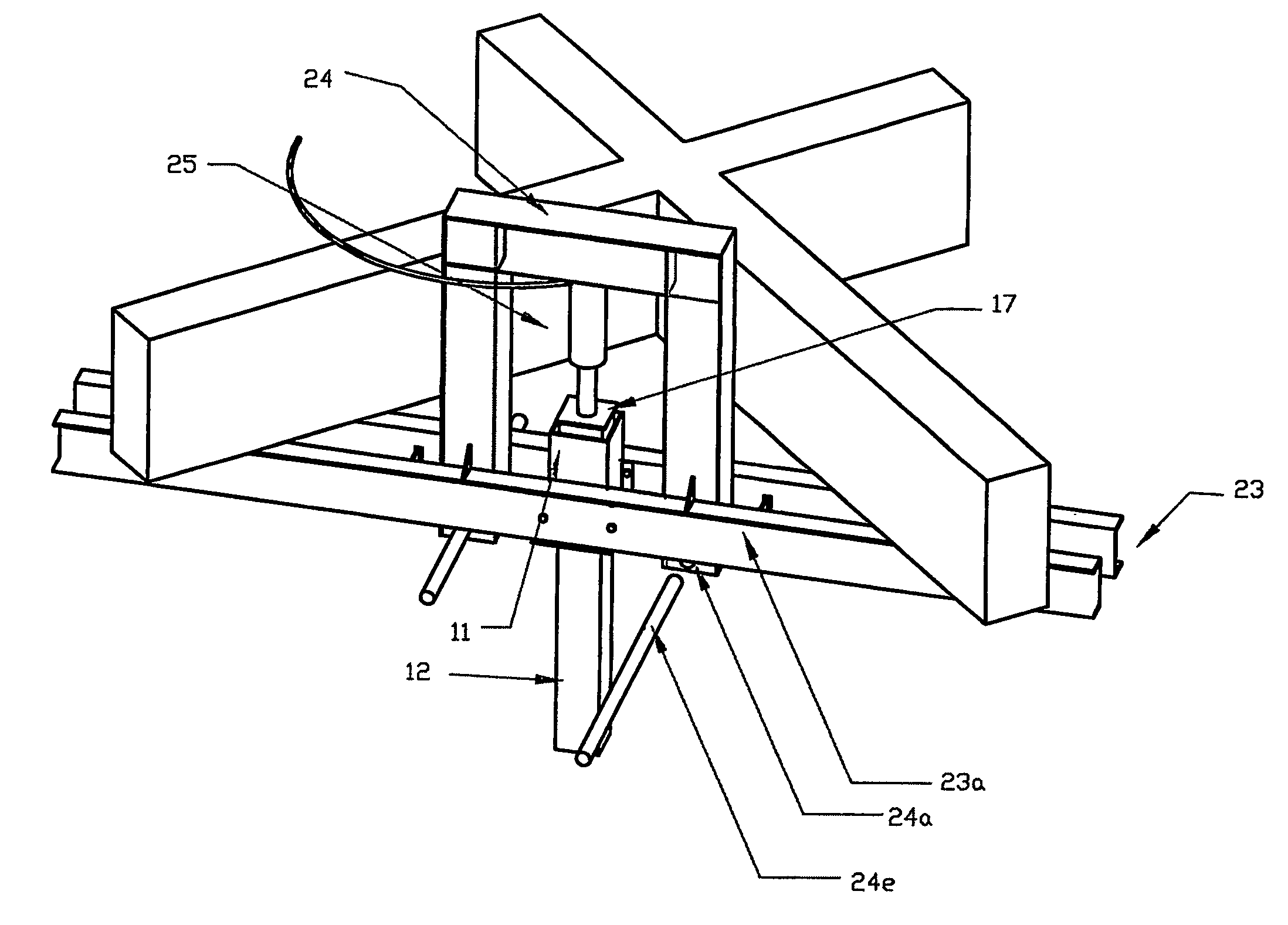
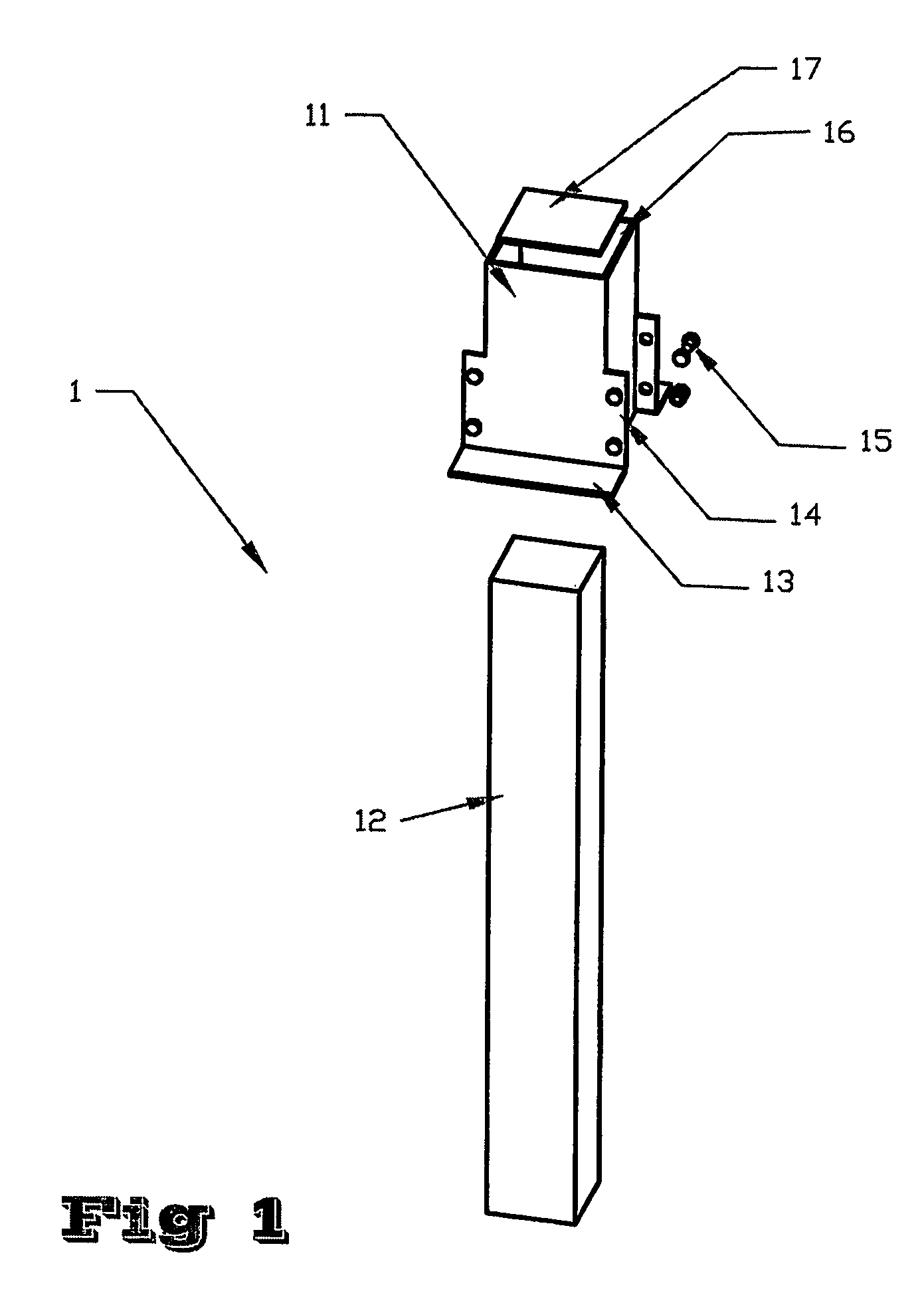
[0050]FIG. 1 shows the components of an underpinning pile (1) according to one embodiment of the present invention. In the broadest aspect of the present invention, the underpinning pile (1) comprises a pile (12), a pile anchor head (11) and a lifting means for lifting the settling foundation. The pile (12) can be any kind of material and shape such as timber, concrete, ex-rail piles or steel pipes.

[0051]The pile anchor head (11) of the present invention is designed to have a rectangular body with a tabular hollow section (16) for accommodating the pile (12). The body is made from two L-sections joined back to back by side plates. Thus, flanges (13) are provided on opposite flat parallel surfaces at sides o...


PUM


Abstract

There is disclosed an underpinning pile to provide an efficient, simple and sure method in driving and lifting the foundation and at the same time securing the direct transference of preload without further loss of preload from the building into the newly completed driven pile. A pile anchor head (11) is provided that receives a pile (12) and is provided with a lifting means (13). The pile anchor head (11) and lifting means (13) receive the building load and transfers it to the pile (12), which allows practically any kind of material and shape of pile (12) to be used.

Description

FIELD OF THE INVENTION[0001]The present invention relates generally to an underpinning pile, especially to an underpinning pile having an improved pile anchor head for an improved pile efficiency and load capacity.BACKGROUND OF THE INVENTION[0002]Prior art teaches various methods for underpinning to strengthen settling foundation, via primarily two types of underpinning, namely the active and passive underpinning pile. Further, most of the methods are adapted for underpinning a wall foundation rather than a typical large pile cap which carries a concentrated load from the structural concrete frame of the building.[0003]In passive underpinning pile, the new pile is inserted adjacent to the existing settling foundation and then is either bonded or connected to the pile cap or footing by means of a cantilever bracket, ties or enlarged footings. The settling foundation is allowed to settle further until the passive underpinning pile becomes loaded gradually with time. Such method has we...

Claims


Application Information

Patent Timeline
Patent Type & Authority Patents(United States)
IPC IPC(8): E02D35/00
CPCE02D35/00
Inventor ONG, CHIN CHAI
Owner ONG CHIN CHAI
Why Eureka
Try Eureka