Electric shock prevention device for electric welding machine
An anti-electric shock and electric welding machine technology, which is applied in arc welding equipment, welding equipment, manufacturing tools, etc., can solve the problem of death by electric shock and achieve rapid tripping and excellent anti-electric shock effect
Active Publication Date: 2012-07-11
左敬民
4 Cites 6 Cited by
AI-Extracted Technical Summary
Problems solved by technology
However, in dangerous occasions such as ballast tank welding operation...
Abstract
An electric shock prevention device for an electric welding machine is provided with a finger ring line, an electric shock prevention circuit, a finger ring line detecting circuit and a transmission switching signal circuit, wherein output of the electric shock prevention circuit and output of the finger ring line detecting circuit are respectively connected with an electric leakage protection unit, the transmission switching signal circuit is connected with the electric leakage protection unit through a required switching circuit, and the finger ring line comprises a core wire, an insulating layer, a shielding layer and an outer insulating layer in a wrapping manner from inside to outside. The electric shock prevention device is rapid and reliable in tripping and excellent in electric shock prevention effect. The simple finger ring signal line (the signal line is sleeved on a finger or held in a hand, or the signal line is connected with a conductor, and then the conductor contacts with the hand or a wrist, an ankle and the like) synchronously and accurately extracts weak electric induction signals when an optional portion of the body of an electric welder is in electric shock, and rapidly drives an electric leakage protector, a specially customized high-power relay or a specially customized contactor to cut off power (a person in electric shock can be protected by driving the high-power relay or the contactor to cut off the power).
Application Domain
Arc welding apparatus
Technology Topic
ContactorElectricity +5
Image
Examples
- Experimental program(1)
Example Embodiment
[0041] An electric shock protection device for an electric welding machine of the present invention will be described in detail below in conjunction with the embodiments and accompanying drawings.
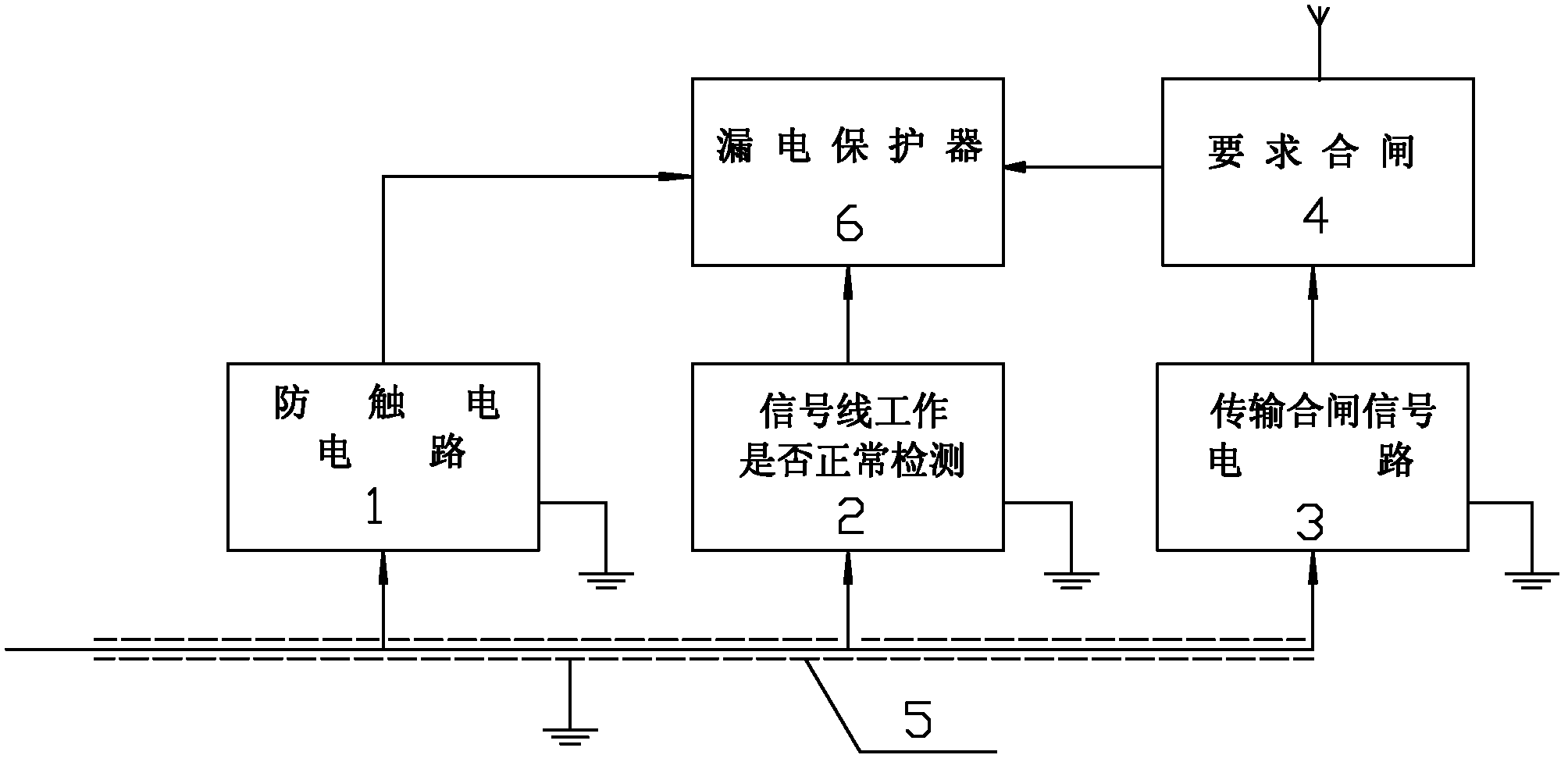
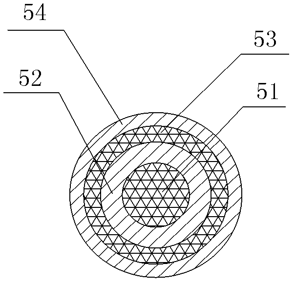
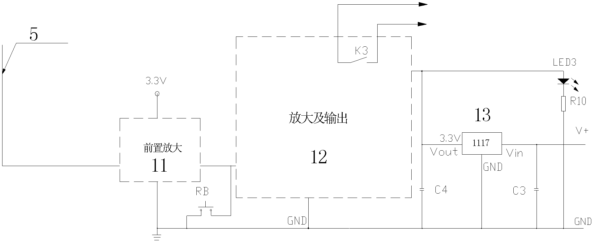
[0042] Electric welding machine anti-shock device of the present invention, as figure 1 As shown, use a simple ring signal line (the signal line is placed on the finger, or held in the palm of the hand; or the signal line is connected to a conductive object, and the conductive object is in contact with the hand or wrist, ankle, etc.), and the welding The weak electric induction signal when any part of the worker's body gets an electric shock is extracted synchronously and accurately, and quickly drives the leakage protector or high-power relay or contactor to cut off the power (driving the high-power relay or contactor to cut off the power can also protect people from electric shock , but the reliability is worse, the power-off speed is slower, and the anti-shock effect is worse.).
[0043] The signal line is also connected in parallel with another signal detection circuit, which is used to detect whether the welder is wearing the ring wire when welding, and whether the ring wire is in good working condition, such as short circuit, open circuit, excessive contact resistance, etc.? As long as the signal line fails to work normally, the signal processing circuit will quickly drive the leakage protector or high-power relay or contactor to cut off the power.
[0044] The signal line can also be connected in parallel with another signal processing circuit, and is used to send a signal to notify relevant personnel to close the switch or directly use it to close the switch. To send a signal, you only need to short-circuit the core wire of the signal line and the external ground shielding wire or use a button switch without a lock to short-circuit.
[0045] Electric welding machine anti-shock device of the present invention, as figure 1 As shown, use a simple ring signal line (the signal line is placed on the finger, or held in the palm of the hand; or the signal line is connected to a conductive object, and the conductive object is in contact with the hand or wrist, ankle, etc.), and the welding The weak electric induction signal when any part of the worker's body gets an electric shock is extracted synchronously and accurately, and quickly drives the leakage protector, high-power relay, and contactor to cut off the power (driving a commercially available high-power relay or contactor to cut off the power supply can also cause electric shock to people. protected, but less reliable).
[0046] The signal line is also connected in parallel with another signal detection circuit, which is used to detect whether the welder is wearing the ring wire when welding, and whether the ring wire is in good working condition, such as short circuit, open circuit, excessive contact resistance, etc.? As long as the signal line fails to work normally, the signal processing circuit will quickly drive the leakage protector or high-power relay or contactor to cut off the power.
[0047] The signal line can also be connected in parallel with another signal processing circuit, and is used to send a signal to notify relevant personnel to close the switch or directly use it to close the switch. To send a signal, you only need to short-circuit the core wire of the signal line and the external ground shielding wire or use a button switch without a lock to short-circuit.
[0048] like figure 1 As shown, a kind of anti-shock device of electric welding machine of the present invention includes, finger ring line 5, the anti-shock circuit 1 that respectively receives the output signal of ring line 5, ring line detection circuit 2 and transmission closing signal circuit 3, described The outputs of the anti-shock circuit 1 and the ring wire detection circuit 2 are respectively connected to the leakage protection unit 6 , and the transmission closing signal circuit 3 is connected to the leakage protection unit 6 through the request closing circuit 4 .
[0049] like figure 2 As shown, the finger ring wire 5 is composed of a core wire 51 , an insulating layer 52 , a shielding layer 53 and an outer insulating layer 54 wrapped in sequence from inside to outside. The finger ring wire 5 can form a composite cable together with the electric welding wire, or it can be routed separately.
[0050] One end of the core wire 51 of the ring wire 5 is connected with the hand, wrist or foot of the protected person, and the other end of the core wire 51 is connected with the electric shock prevention circuit 1, the ring wire detection circuit 2 and the input end of the transmission closing signal circuit 3 , The closing signal is sent out through the short circuit between the core wire 51 and the shielding wire.
[0051]The core wire 51 of the ring wire 5 is directly connected in parallel to the input terminals of unit circuits such as the electric shock prevention circuit 1, the ring wire detection circuit 2, and the transmission closing signal circuit 3, and the output of the electric shock prevention circuit 1 and the ring wire detection circuit 2 are used for When an electric shock occurs or the signal line does not work normally, the power switching device trips, and the transmission closing signal circuit 3 is used to transmit a closing signal to inform relevant personnel to close or directly close.
[0052] like image 3 As shown, the anti-shock circuit 1 includes a preamplifier circuit 11 connected to the ring line 5, an amplifying output circuit 12 connected to the preamplifying circuit 11, a 1117 voltage regulator 13 connected to the amplifying output circuit 12, And the light emitting diode LED3 connected with the amplifier output circuit 12 .
[0053] like Figure 4 , Figure 5 As shown, the preamplifier circuit 11 includes an optocoupler G1, pin 1 of the optocoupler G1 is connected to a 3.3V power supply through a resistor R12, pin 5 is connected to a 3.3V power supply through a resistor R13, and pin 4 is used as an output connection The input terminal of the amplified output circuit 12, the 4 pins are also connected to the ground through the capacitor C2 and the resistor R3 respectively, the 2 pins are connected to the collector of the triode T1, the emitter of the triode T1 is grounded, and the base is connected to the ring line 5 through the diode D1 and the resistor R1 in turn , the base is grounded through capacitor C1, grounded through resistor R2, and grounded through diode D2 and diode D3 in series, and the base is also connected to a 3.3V power supply in series through test button TB and resistor R8 in turn; the photocoupler Device G1 is an optocoupler output by a triode or an optocoupler output by a Darlington.
[0054] like Image 6 , Figure 7 As shown, the amplified output circuit 12 includes a photocoupler G2, a triode T2 whose base is connected to pin 4 of the photocoupler G2, and a relay K3 connected to the collector of the triode T2. The photocoupler G2 pin 2 of the SCR 3T1 is grounded, the trigger terminal of the thyristor 3T1 is connected to the output terminal of the preamplifier circuit 11, the trigger terminal is grounded through the RB reset button, and pin 1 of the photocoupler G2 is connected to 3.3 V power supply, pin 5 is connected to a 3.3V power supply through a resistor R11, the emitter of the triode T2 is grounded, and the collector of the triode T2 is also connected to a 3.3V power supply in series with a light-emitting diode through a resistor R6, and connected to a 3.3V power supply through a diode. V power supply, the other end of the relay K3 is connected to a 3.3V power supply, and the normally open contact of the relay K3 is connected to the leakage protection unit 6; the photocoupler G2 is a photocoupler output by a triode or a photocoupler output by a Darlington device.
[0055] like Figure 8 As shown, the ring line detection circuit 2 includes a first AND pre-processing circuit 21 and a second AND pre-processing circuit 22, the signal input end of the AND pre-processing circuit 21 is connected to the ring line 5, and the The input end of the second AND gate pre-processing circuit 22 is connected to the current transformer C, and the output ends of the first AND gate pre-processing circuit 21 and the second AND gate pre-processing circuit 22 are connected to a 3.3V power supply, and the first AND gate The pre-processing circuit 21 is also grounded through the capacitor C4, and the first AND gate pre-processing circuit 21 and the second AND gate pre-processing circuit 22 are respectively connected to the AND gate J1, and the other end of the AND gate J1 is connected to the gate through the resistor R16. The series connection of the resistor R18 is connected to the base of the transistor T3, and the terminal of the AND gate J1 is also grounded through the series connection of the resistor R16 and the capacitor C5, and grounded through the series connection of the resistor R16 and the resistor R17, and the emitter of the transistor T3 is grounded. The electrodes are connected to the 3.3V power supply through the diode D5 and the relay K2 respectively, and the normally open contact of the relay K2 is connected to the leakage protection unit 6 .
[0056] The current transformer C is set on the output end of the electric welding machine, and is used to take the working signal of the welding machine and send it to the ring line detection circuit and the energy-saving circuit in parallel. The induction signal of the core wire of the ring wire cannot be received during welding, and the two input terminals of the AND gate are at high level, driving the triode T3 to make the relay K2 act, and pushing the tripping coil to cut off the power.
[0057] like Figure 9 As shown, the composition of the first AND pre-processing circuit 21 is as follows: one end of the resistor R1 is connected to the ring line 5, the other end is grounded through the diode D1, grounded through the series connection of the capacitor C1, the diode D2 and the diode D3, and connected through the The series connection of capacitor C1, diode D2 and resistor R13 is grounded, the base of the Darlington transistor T7 is connected through the series connection of capacitor C1 and resistor R3, the ground is connected through the series connection of capacitor C1, diode D4 and resistor R4, and the capacitor C1 Connect the 3.3V power supply in series with the resistor R2, the emitter of the Darlington transistor T7 is connected to the base of the transistor T4 through the resistor R6, the emitter is also grounded through the resistor R6 and the resistor R5 in turn, and the Darlington transistor T7 The collector is connected to a 3.3V power supply, the emitter of the triode T4 is grounded, the collector is connected to pin 2 of the photocoupler G3 through a resistor R7, pin 1 and pin 4 of the photocoupler G3 are connected to a 3.3V power supply, and pin 3 is connected to a resistor R8 Connect the base of the triode T5, the emitter of the triode T5 is grounded, the collector is connected to the 3.3V power supply through the series connection of the resistor R9 and the resistor R10, and the collector is also connected to the AND gate J1 through the resistor R9; The composition of the processing circuit 22 is: the two input terminals of the rectifier bridge H1 are connected to the current transformer C, the positive output pole is connected to the resistor R11, the negative pole of the output is grounded, the other end of the resistor R11 is grounded respectively through the capacitor C2, and grounded through the resistor R12. This end is also connected to pin 1 of the optocoupler G4, pin 4 of the optocoupler G4 is connected to one end of resistor R19, the other end of R19 is connected to a 3.3V power supply, pin 2 is grounded through resistor R14, pin 3 is connected to AND gate J1 , the 3 pins are also grounded through the resistor R15 and grounded through the capacitor C3.
[0058] like Figure 10 As shown, the composition of the first AND pre-processing circuit 21 is as follows: one end of the resistor R21 is connected to the ring line 5, the other end is grounded respectively through the diode D21, grounded through the series connection of the capacitor C21, the diode D22 and the diode D23, and grounded through the serial connection of the capacitor C21, the diode D22 and the diode D23. The series connection of capacitor C21, diode D22 and resistor R24 is grounded, the base of the transistor T8 is connected through the series connection of capacitor C21 and resistor R23, the ground is connected through the series connection of capacitor C21, diode D24 and resistor R25, and the capacitor C21 and resistor R22 are connected in series connected in series with a 3.3V power supply, the emitter of the triode T8 is connected to the base of the triode T9 through the resistor R27, the emitter is also grounded through the resistor R27 and the resistor R26 in turn, and the collector of the triode T8 is connected to the 3.3V power supply. The emitter of the triode T9 is grounded, the collector is connected to the 2 pin of the photocoupler G5 output by Darlington through the resistor R28, the 1 pin and 4 pin of the photocoupler G5 are connected to the 3.3V power supply, and the 3 pin is connected to the triode T10 through the resistor R29 The base, the emitter of the triode T10 is grounded, the collector is connected to the 3.3V power supply through the series connection of the resistor R31 and the resistor R30, and the collector is also connected to the AND gate J1 through the resistor R31; the second AND gate pre-processing circuit 22 The composition is: the two input ends of the rectifier bridge H2 are connected to the current transformer C, the positive output is connected to the resistor R32, the negative output is grounded, the other end of the resistor R32 is grounded through the capacitor C22, and the resistor R33 is grounded respectively, and the ends of the resistor R32 are respectively connected to the ground. Connect the resistor R34 and the base of the transistor T13, the other end of the resistor R34 is connected to the base of the transistor T11, one end of the resistor R35 is connected to the 3.3V power supply and the other end is respectively connected to the collector of the transistor T11 and the base of the transistor T12, and the transistor T11 And the emitter of the triode T12 is grounded, the collector of the triode T12 is connected to the AND gate J1 through the resistor R37, the emitter of the triode T13 is grounded through the capacitor C23, and connected to the AND gate J1, and the collector of the triode T13 is connected to the 3.3V power supply through the resistor R36 .
[0059] like Figure 11 As shown, the described transmission closing signal circuit 3 includes a photocoupler G6, and the 2 pins of the photocoupler G6 pass through the diode string D31 (the number of the diodes is determined by experiments, so as not to affect the electric shock prevention circuit for It is also possible to add a second diode before the diode D1 at the input end of the anti-shock circuit) respectively connect the ring line 5, the anti-shock circuit 1 and the ring line detection circuit 2, pin 1 is connected to the 3.3V power supply through resistor R38, and pin 3 is connected to the 3.3V power supply through resistor R38. The resistor R40 is connected to the base of the triode T14, grounded through the resistor R39 and the reset key F, and connected to the trigger terminal of the thyristor 3T2 through the resistor R39, and the 4 pin is connected to the 12V power supply, the emitter of the triode T14 is grounded, and the collector passes through The relay K1 is connected to a 12V power supply, the normally open contacts K1-1 and K1-2 of the relay K1 are connected to the closing circuit 4, one end of the thyristor 3T2 is grounded, and the other end is respectively connected to the light-emitting diode D32 and the speaker Y, The other end of the speaker Y is connected to a 3.3V power supply, and the other end of the LED D32 is connected to a 3.3V power supply through a resistor R42.
[0060] When the ring wire needs to be closed, only the core wire of the ring wire needs to be short-circuited to the ground, and the relay K1 can control and send a closing signal. The relay K1 uses a group of normally open contacts to send a wireless signal to request closing, or the relay K1 is omitted to send an audible and visual alarm to request closing.
[0061] like Figure 12 , Figure 13 , Figure 14 As shown, the required closing circuit 4 includes a control unit, a handheld display unit and a wireless transmitting and receiving unit, wherein the control unit and the handheld display unit are respectively connected to corresponding wireless transmitting and receiving units, and the described The control unit is respectively connected to the transmission closing signal circuit 3 and the leakage protection unit 5. The wireless transmitting and receiving unit adopts the wireless transmitting chip U1 of CC1000, and the control unit includes a control chip U2, a photocoupler G7 and Optocoupler G8, pin 1 of the control chip U2 is grounded through resistor R41, pin 2 is grounded through capacitor C30, pin 4 is grounded, pin 5 is connected to pin 6 through crystal capacitor X2, pin 7 is connected to 3V power supply through resistor R42, and Ground through capacitor C31, pin 8, pin 13, pin 14, pin 15 and pin 17 are respectively connected to wireless transmitter chip U1, pin 14 is also connected to 3V power supply through resistor R47, and grounded through switch K6, pin 9 is grounded through switch K4, and Connect the 3V power supply through the resistor R51, connect the 10-pin to the 3V power supply through the resistor R52, and in turn pass the normally open contact K1-1 of the transmission closing signal circuit 3 and the normally closed contact of the relay K to ground, and connect the 12-pin to the photocoupler G8 2 pins, 16 pins are connected to 3V power supply through resistor R48, and grounded through switch K2, 18 pins are connected to 3V power supply through resistor R50, and grounded through switch K3, 19 pins are connected to 2 pins of photocoupler G7, 20 pins pass through the light in turn Diode D10 and resistor R45 are connected to 3V power supply, pin 1 of photocoupler G7 is connected to 3V power supply through resistor R46, pin 3 is connected to 3V power supply through resistor R43, pin 4 is connected to the base of transistor T15, the emitter of transistor T15 is grounded, and the collector The coil of relay K4 is connected to 3V power supply, pin 1 of photocoupler G8 is connected to 3V power supply through resistor R49, pin 3 is connected to 3V power supply through resistor R44 and normally open contact K1-2 of transmission closing signal circuit 3 in turn, and pin 4 is connected to 3V power supply through the coil of relay K4. Connect the trigger end of thyristor 3T3, one end of thyristor 3T3 is connected to relay K, the other end is grounded, pin 4 is also grounded through manual reset switch B, and the other end of relay K is connected to the normally open contact K1-2 of transmission closing signal circuit 3 3V power supply,
[0062] When the switch-on signal is required to be sent out, within the short-circuit time between the core wire of the ring wire and the shielding wire, the wireless signal required to switch on is sent out at a certain time interval. The time interval is guaranteed by the software. The person holding the wireless display device receives the request to close After the gate signal, press the confirmation answer button B, and then close the gate. After the confirmation button is pressed, the feedback wireless information (sent once every shorter time interval) is received by the wireless device required to close the gate, and the 12 pin of U2 is low. Potential, if the command to close is still being transmitted at this time, the K relay is energized due to the closure of K1-2, and its normally closed contact is disconnected, cutting off the continuous transmission of the wireless signal required to close (this is mainly to deal with special In some cases, the core wire of the ring wire and the shielding wire are short-circuited for a long time, and the closing command is required to be busy for a long time, so the channel should be vacant).
[0063]The normally open contact of the relay K4 is connected to the leakage protection unit 6; the handheld display unit includes a chip U3, and pin 1 of the control chip U3 is grounded through a resistor R54, pin 2 is grounded through a capacitor C32, and pin 4 of the control chip U3 is grounded through a capacitor C32. Pin 5 is connected to pin 6 through crystal capacitor X3, pin 7 is connected to 3V power supply through resistor R53, and grounded through capacitor C33, pin 11 is grounded through unified power switch B2, pin 8, pin 13, pin 14, pin 15 and pin 17 The pins are respectively connected to the wireless transmitter chip U1, the 14 pins are also connected to the LCD interface J2 and the LCD interface J3, the 9 pins are respectively connected to the LCD interface J2 and the LCD interface J3, the 10 pins are connected to the LCD interface J3, and the 12 pins are connected to the LCD screen Interface J2, pins 16 and 18 are respectively connected to LCD interface J2 and LCD interface J3, pin 19 is connected to 3V power supply through resistor R56, and grounded through confirmation button B, pin 20 is in turn passed through light-emitting diode D33 or 3V ringing The resistor R55 is connected to a 3V power supply, the LCD screen interface J2 and the LCD screen interface J3 are respectively connected to the LCD screen, and a 555 circuit U4 is also provided, and the 555 circuit U4 is connected to the LCD screen interface J3 through the chip U5.
[0064] like Figure 15 As shown, the leakage protection unit 6 includes a power cord 6-3 with one end connected to the power supply and the other end connected to the electric welding machine. The power input end of the power cord 6-3 is provided with a trip switch 6-1. The power line 6-3 on the output side of the trip switch 6-1 is covered with a leakage protection magnetic ring 6-2, wherein the low voltage end of the power input side of the trip switch 6-1 described above is Respectively through the normally open contact of the relay K3 of the anti-shock circuit 1, the normally open contact of the relay K2 of the ring line detection circuit 2, the normally open contact of the relay K4 of the closing circuit 4 and the timing switch K1' to connect the resistor R59 , the other end of the resistor R59 is connected to the high voltage end of the power line 1-3 at the welding machine end.
[0065] In the magnetic ring of the current transformer with leakage protection for electric welding machine, two wires are generally connected: 380V, one input and one output. When used in conjunction with the energy-saving device, when the timer is up, K1' closes, driving the leakage protection trip to cut off the power.
[0066] Used in conjunction with the anti-shock device, when the welder gets an electric shock, the electric shock induction signal picked up by the core wire of the ring wire is sent to the anti-shock circuit, which drives K3 to close and cuts off the 380V power supply; if the ring wire works faulty, the ring wire signal line detection circuit detects After that, drive K2 to close and cut off the power supply. If necessary, the person holding the wireless display device can press the B2 button to issue a unified power-off command. After receiving the wireless unified power off command, Figure 13 The pin 19 of the U2 chip becomes low potential, so that K4 closes and cuts off the power supply of the welding machine. This function is used for unified power outage management of a large number of welding machines.
PUM


Description & Claims & Application Information
We can also present the details of the Description, Claims and Application information to help users get a comprehensive understanding of the technical details of the patent, such as background art, summary of invention, brief description of drawings, description of embodiments, and other original content. On the other hand, users can also determine the specific scope of protection of the technology through the list of claims; as well as understand the changes in the life cycle of the technology with the presentation of the patent timeline. Login to view more.
Similar technology patents
Anti-scour device of chloromethane waste heat recovery device
Owner:HUAIYIN INSTITUTE OF TECHNOLOGY +1
Multifunctional ice and snow removing device for municipal administration
Owner:苏州荔记得机械工程科技有限公司
Classification and recommendation of technical efficacy words
- Good anti-shock effect
Anti-scour device of chloromethane waste heat recovery device
Owner:HUAIYIN INSTITUTE OF TECHNOLOGY +1
Multifunctional ice and snow removing device for municipal administration
Owner:苏州荔记得机械工程科技有限公司