Polishing device

A technology of polishing device and mounting seat, which is applied in the direction of grinding/polishing safety device, surface polishing machine tool, grinding/polishing equipment, etc. It can solve the problems of inability to rotate in multiple directions, time-consuming and labor-intensive, and inability to adapt to various needs. To achieve the effect of convenient and fast operation

Inactive Publication Date: 2014-01-08
SUZHOU PREMIER ELECTRICAL APPLIANCE CO LTD
View PDF4 Cites 0 Cited by
  • Summary
  • Abstract
  • Description
  • Claims
  • Application Information

AI Technical Summary

Problems solved by technology

The disadvantages of this rotating mechanism are: 1. Although the circumferential rotation can be realized between the connecting pipe 8 and the cover plate 2 and the housing 1, the up and down rotation cannot be realized, so it cannot adapt to various needs in the polishing process, and cannot be flexible 2. The operation is cumbersome, and the installation cover 10 must be removed and installed every time the angle is adjusted, which is time-consuming and labor-intensive

Method used


Image

  • Polishing device
  • Polishing device
  • Polishing device

Examples


Embodiment

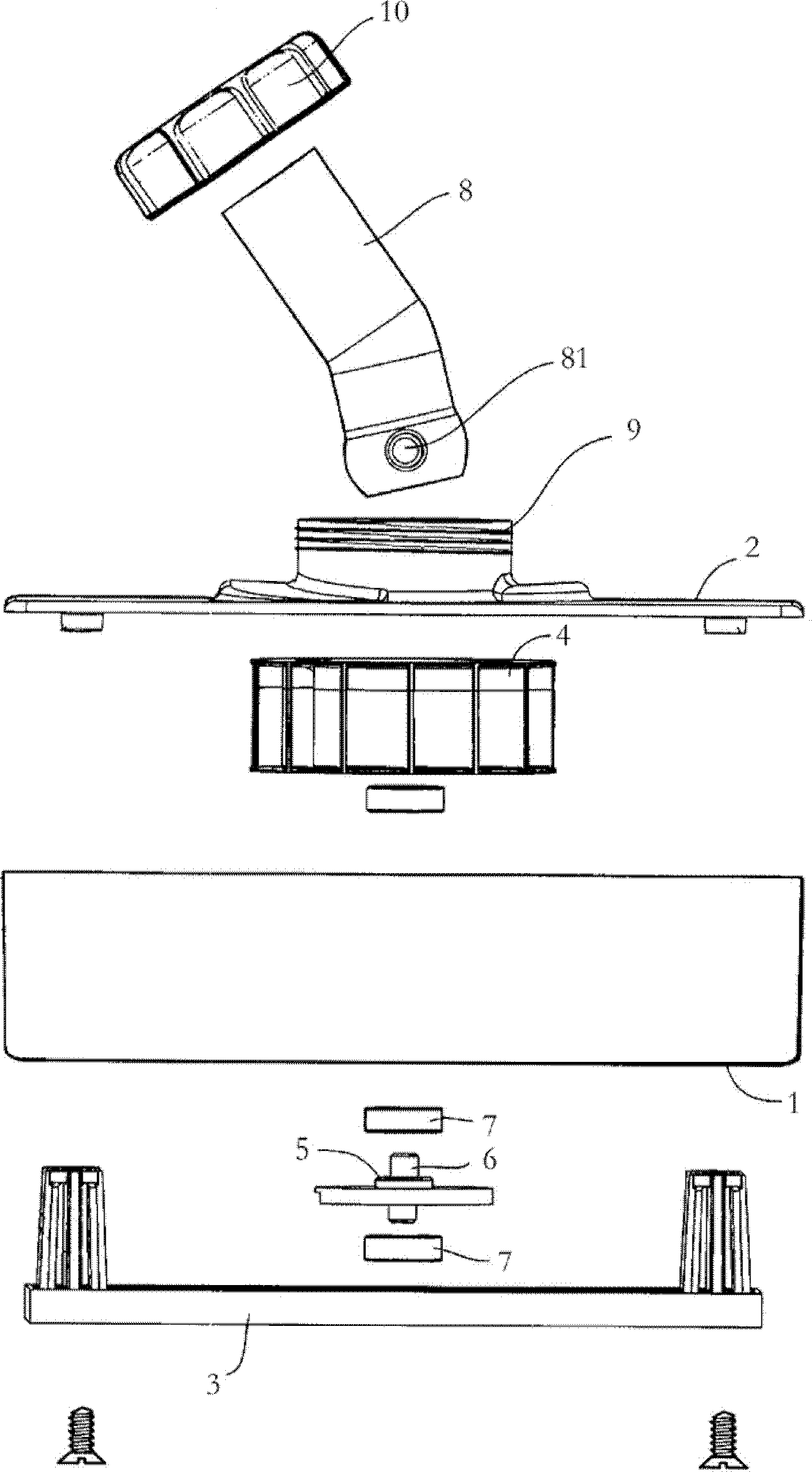
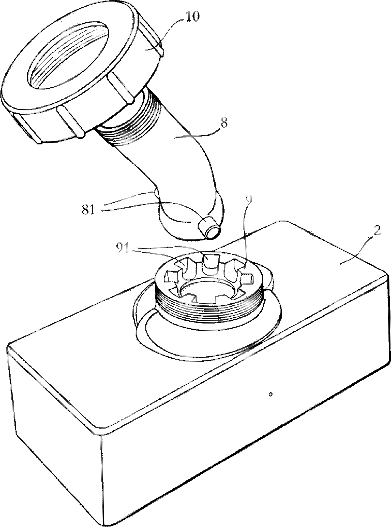
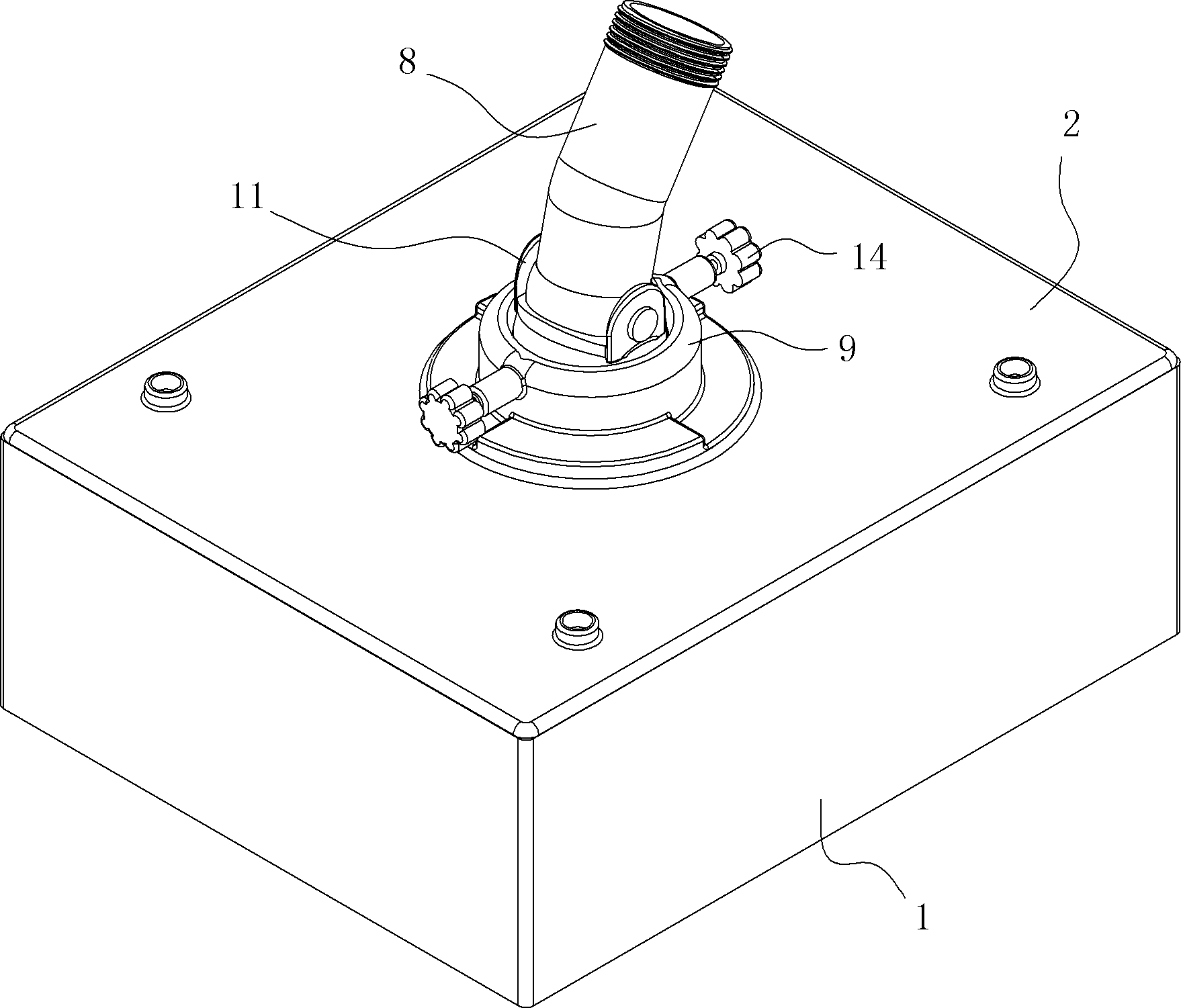
[0024] Embodiment: A kind of polishing device comprises shell 1, shell 1 top has cover plate 2, and shell 1 bottom has polishing chassis 3, and shell 1 is provided with fan blade 4, rotating shaft 6 and is used for driving polishing chassis 3 The moving eccentric disk 5, the cover plate is provided with a connecting pipe rotation mechanism, the connecting pipe rotating mechanism includes a connecting pipe 8 and a mounting seat 9 arranged on the cover plate 2, the bottom of the connecting pipe 8 is horizontally pinned with a joint 11, and the joint 11 There are several pairs of sockets 111 on the peripheral wall, and a pair of opposite elastic pins 12 are provided on both sides of the mounting base 9, and the mounting base 9 is connected with the joint 11 by inserting the elastic pins 12 into a certain pair of sockets 111 of the joint 11. After locking and positioning, pull the two elastic bolts 12 outward, and then the elastic bolts 12 will withdraw from the socket 111 to reali...


PUM


Abstract

The invention discloses a polishing device, which comprises a shell, wherein an upper part of the shell is provided with a cover plate; a lower part of the shell is provided with a polishing base plate; fan blades, a rotating shaft and an eccentric disc for driving the polishing base plate to move are arranged in the shell; an adapter rotating mechanism is arranged on the cover plate; the adapter rotating mechanism comprises an adapter and a mounting base arranged on the cover plate; the bottom of the adapter is in pin joint with a joint transversely; a plurality of pairs of jacks are formed on a peripheral wall of the joint; two sides of the mounting seat are provided with a pair of elastic pins opposite to each other; the mounting seat is inserted into a certain pair of jacks of the joint through the elastic pins so as to realize locking and positioning between the mounting seat and the joint, and the two elastic pins are pulled outwards, so that the elastic pins exit from the jacks, and unlocking is realized. The elastic pins are inserted into or exit from the jacks of the joint, so that locking and unlocking between the mounting seat and the joint are realized, and the device is conveniently and rapidly operated and is time-saving and labor-saving.

Description

technical field [0001] The invention relates to a vacuum polishing machine, in particular to a polishing device. Background technique [0002] As a kind of polishing equipment, polishing machine is widely used in mechanical processing. During the polishing process of the workpiece, the polishing machine will generate a lot of dust. This makes the working environment poor, and inhaling excessive dust will also affect the health of the operating workers. For this reason, people have devised vacuum polishing machine, and it comprises vacuum device and polishing device, as figure 1 and figure 2 As shown, the polishing device includes a housing 1, the upper part of the housing 1 has a cover plate 2, and the lower part has a polishing chassis 3, and the housing 1 is provided with a fan blade 4, an eccentric disk 5 and a rotating shaft 6, and the fan blade 4 and the eccentric The disk 5 is fixed on the rotating shaft 6, and the rotating shaft 6 is sleeved in the bearing 7 of t...

Claims


Application Information

Patent Timeline
Patent Type & Authority Patents(China)
IPC IPC(8): B24B55/06B24B29/00
Inventor 褚小明沈斌王新华
Owner SUZHOU PREMIER ELECTRICAL APPLIANCE CO LTD
Why Eureka
Try Eureka