
Heavy Duty Pneumatic Tires

A technology for pneumatic tires and tires, which is applied to tire parts, tire treads/tread patterns, transportation and packaging, etc. It can solve the problems of reducing drainage performance, reducing main groove 3, and deformation, so as to reduce stone inclusion and reduce Effect of contact area and pressing force

Active Publication Date: 2016-02-24
SUMITOMO RUBBER IND LTD
View PDF4 Cites 0 Cited by
  • Summary
  • Abstract
  • Description
  • Claims
  • Application Information

AI Technical Summary

Problems solved by technology

[0005] However, the above-mentioned protrusion 35 is easily deformed due to the contraction of the main groove 3 when it is grounded, and thus cannot sufficiently reduce stone inclusions.
In addition, since the protrusion 35 reduces the groove volume of the main groove 3, there is also the problem that the drainage performance is easily reduced.

Method used


Image

  • Heavy Duty Pneumatic Tires
  • Heavy Duty Pneumatic Tires
  • Heavy Duty Pneumatic Tires

Examples


Embodiment

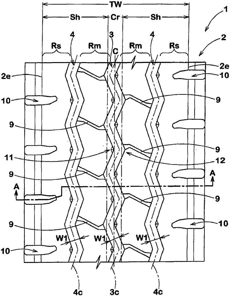
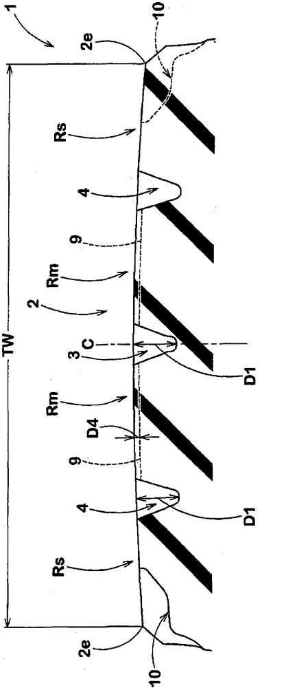
[0076] Manufacturing has figure 1 The tires having the basic structure shown in Table 1 and having the tread portion of the central main groove shown in Table 1, and their performances were evaluated. In addition, as a comparison, it is also necessary to have Figure 10 The shown tire (comparative example 1) of the tread portion of the projection (length: 6.5 mm, width: 3.0 mm, height: 3.5 mm) for preventing stone trapping, and the angle of the gently sloped portion of the tread side from the concave corner to the convex corner The tires (Comparative Example 2) whose parts gradually increased were also subjected to the same test. Among them, the common specifications are as follows.

[0077] Tire size: 11.00R20

[0078] Rim size: 8.0V×20

[0079] Tread width TW: 226mm

[0080] Central Main Ditch:

[0081] Groove width W1: 16mm

[0082] Groove depth D1: 17mm

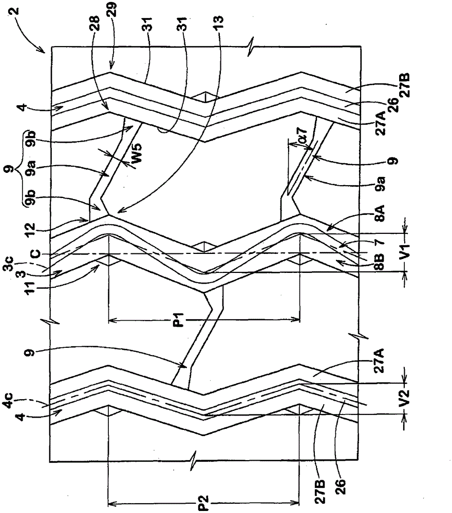
[0083] Sawtooth swing V1: 16mm

[0084] Ratio (V1 / TW): 7%

[0085] Sawtooth pitch P1: 79mm

[0086] Ratio (P...


PUM


Abstract

PROBLEM TO BE SOLVED: To provide a pneumatic tire for a heavy load capable of reducing stone trapping while maintaining drainage performance.SOLUTION: In the pneumatic tire for the heavy load, at least one center main groove 3 continuously extending in a zigzag shape to a center range Cr. The center main groove 3 includes a groove bottom 7 and a pair of groove walls 8A, 8B extending from the groove bottom 7 to a tread step-on surface 2t. The respective groove walls 8A, 8B include groove bottom side steeply inclined parts 16A, 16B and step-on surface side gently inclined parts 17A, 17B which extend from the outer ends 16o, 16o in the tire radial direction of the groove bottom side steeply inclined parts 16A, 16B to the tread step-on surface 2t and extend at the larger angles α2, α3 than the groove bottom side steeply inclined parts 16A, 16B. The groove width W1 of the groove bottom side steeply inclined parts 16A, 16B is 2-8 mm. The respective groove walls 8A, 8B include an inner corner part of the center main groove 3 and an outer corner part bending to the opposite side to the groove center line. The larger angles α2, α3 of the step-on surface side gently inclined parts 17A, 17B gradually increase from the outer corner part to the inner corner part.

Description

technical field [0001] The present invention relates to a pneumatic load tire capable of maintaining drainage performance and reducing stone inclusion. Background technique [0002] In order to ensure drainage performance, one or more wide main grooves extending continuously in the tire circumferential direction are provided on the tread portion of the pneumatic tire. For example, when the main ditch is driven at a construction site or the like, a so-called stone trap, in which small stones are caught and kept in a state where the small stones are caught, is likely to occur. Such stone inclusions are particularly likely to occur in heavy-duty pneumatic tires with a large tread pressure and a large groove depth, so there is a problem that rubber chips or cracks occur near the main groove. [0003] As a technique for suppressing such stone inclusions, such as Figure 10 As shown, it is proposed that at the bottom of the main groove 3 and at a position separated from the groov...

Claims


Application Information

Patent Timeline
Patent Type & Authority Patents(China)
IPC IPC(8): B60C11/13
CPCB60C11/01B60C11/04B60C11/13
Inventor 李庆茂
Owner SUMITOMO RUBBER IND LTD
Learn More