Clogging preventing method for drainage channel based on underground high-flow-capacity drainage system

A drainage channel and drainage system technology, applied in soil protection, infrastructure engineering, construction, etc., can solve the problems that cannot meet the actual requirements of the total project, complex technical requirements, restrictions, etc.

Active Publication Date: 2014-09-10
HOHAI UNIV
View PDF5 Cites 0 Cited by
  • Summary
  • Abstract
  • Description
  • Claims
  • Application Information

AI Technical Summary

Problems solved by technology

However, under the requirements of the tensile strength of the plastic drainage board, the improvement of its core and filter membrane is also limited to a certain extent, and the problem of silting of the drainage board cannot be solved well; for the improvement of the molding and bonding method of the plastic drainage board, To a certain extent, it solves the blockage in the plate core caused by its own forming gaps and other factors, but as far as the ultra-soft soil with a large content of viscous fine particles is concerned, this improvement has little effect on the blockage of the filter membrane
Generally speaking, the traditional anti-silting method of plastic slabs is to prevent silting underground. The main considerations are the seamless formation of drainage channels and the reasonable adjustment of the surface structure of the filter membrane in order to reduce plate-shaped silting and fine particles of the filter membrane. Dependence, its technical requirements are relatively complex and the treatment effect is difficult to guarantee, and cannot meet the actual requirements of the general project

Method used


Image

  • Clogging preventing method for drainage channel based on underground high-flow-capacity drainage system
  • Clogging preventing method for drainage channel based on underground high-flow-capacity drainage system
  • Clogging preventing method for drainage channel based on underground high-flow-capacity drainage system

Examples


Embodiment Construction

[0030] Specific implementation examples

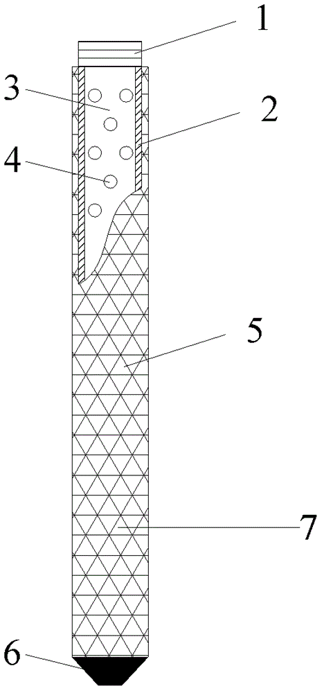
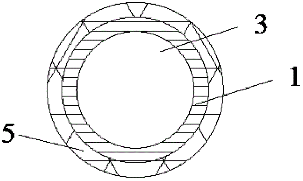
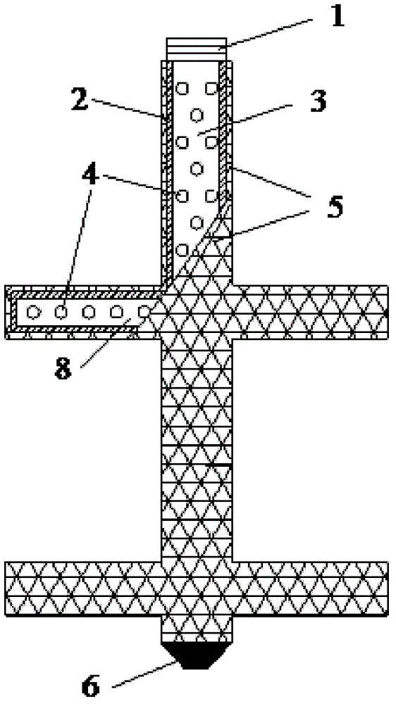
[0031] figure 1 It is the front view and section view of the one-way vertical large water discharge body, figure 2 yes figure 1 top view of image 3 Front view and sectional view of vertical drainage body with horizontal drainage channels; Figure 4 yes image 3 top view; see Figure 1-4 As shown, the drainage channel anti-silting method based on the large underground water flow drainage body, wherein the mentioned underground large water flow drainage body includes a vertical drainage body skeleton 2, and the skeleton material of the drainage body can be selected from iron, steel or plastic ( Such as PVC, PE or HDPE), and the filter cloth or filter membrane with a certain equivalent pore size is attached to the skeleton of the drainage body by artificial binding or hot-melt molding to form a vertical one-way large-flow drainage body 7, Connect the flexible permeable pipe 19 to the upper interface 1 of the vertical drainage bo...


PUM


Abstract

The anti-silting method for drainage channels based on the underground large-flow drainage system is characterized in that it includes the following steps: After connecting the upper opening of the large-flow drainage body with a soft permeable pipe, press it into the ultra-soft soil to be treated until the design depth or the hard shell layer , reserve a section of soft permeable pipe higher than the ground; connect the soft permeable pipe to the drainage branch pipe, and connect the drainage branch pipe to the main drainage pipe, then connect the main drainage pipe to the water inlet of the sedimentation box, and the water outlet of the sedimentation box to connect The other section of the drainage main pipe is connected to the pump and the drainage pipe; and the sealing film and pressure groove are laid in the area where the drainage body is laid; the pump is turned on to vacuumize; according to the supersoft soil surface settlement rate and the expected treatment effect, choose the time to stop vacuuming . It can meet the requirements of the construction period and the uniformity of soil strength after drainage consolidation treatment, and realize the anti-silting treatment under the new idea of ​​"fine particle dredging".

Description

technical field [0001] The invention is an anti-silting method for a drainage channel based on an underground large-flow drainage pipe body, which is suitable for rapid water-soil separation or consolidation drainage pretreatment projects of ultra-soft soil such as dredging and filling soil, dredging silt and mud. Background technique [0002] With the development of tidal flat reclamation and construction in China, especially after my country’s “Twelfth Five-Year Plan” proposed to promote the development of marine economy, the requirements for the area of ​​the land area near the sea and the speed of development will inevitably increase, and land reclamation is one of the main measures. . Taking the reclamation project in Zhejiang as an example, during the "Eleventh Five-Year Plan" period, the total investment in reclamation was 20.2 billion yuan, and the completed reclamation area was 631,000 mu, which was 162% of the "Tenth Five-Year Plan". Reclamation of more than 1 mill...

Claims


Application Information

Patent Timeline
Patent Type & Authority Patents(China)
IPC IPC(8): E02D3/10
Inventor 陈永辉刘汉龙陈庚王新泉张俊楠
Owner HOHAI UNIV
Why Eureka
Try Eureka